Tactile sensor element and sensor array

a sensor array and tactile technology, applied in the field of sensors, can solve the problem of relative high cost of manufacturing and packaging

Inactive Publication Date: 2006-01-26
LEAP TECH APS
View PDF51 Cites 37 Cited by
  • Summary
  • Abstract
  • Description
  • Claims
  • Application Information

AI Technical Summary

Benefits of technology

[0005] It is an object of the invention to provide a novel tactile sensor element and a novel tactile senso

Problems solved by technology

Common to these known sensors are relatively

Method used


Image

  • Tactile sensor element and sensor array
  • Tactile sensor element and sensor array
  • Tactile sensor element and sensor array

Examples


Embodiment Construction

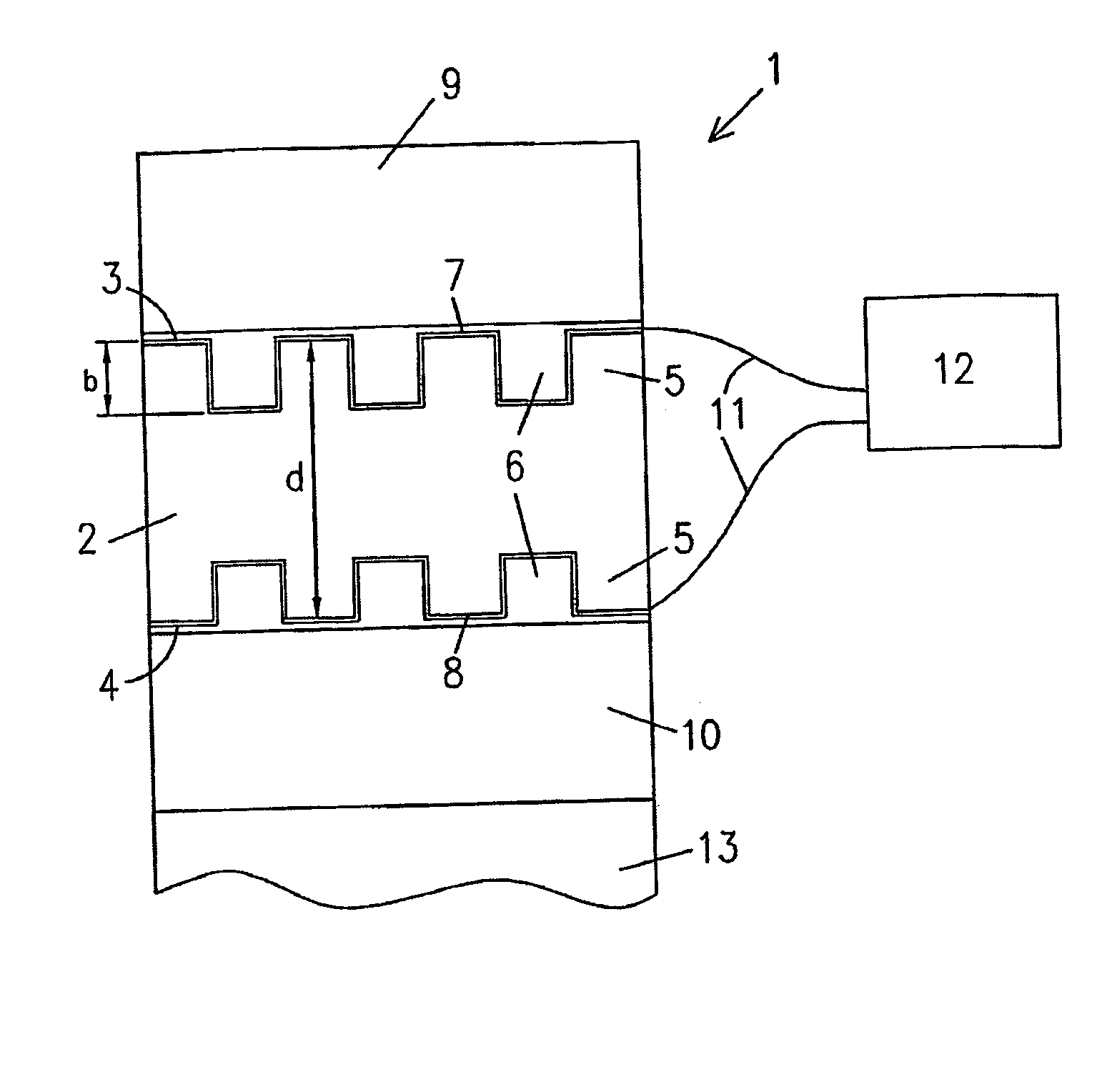
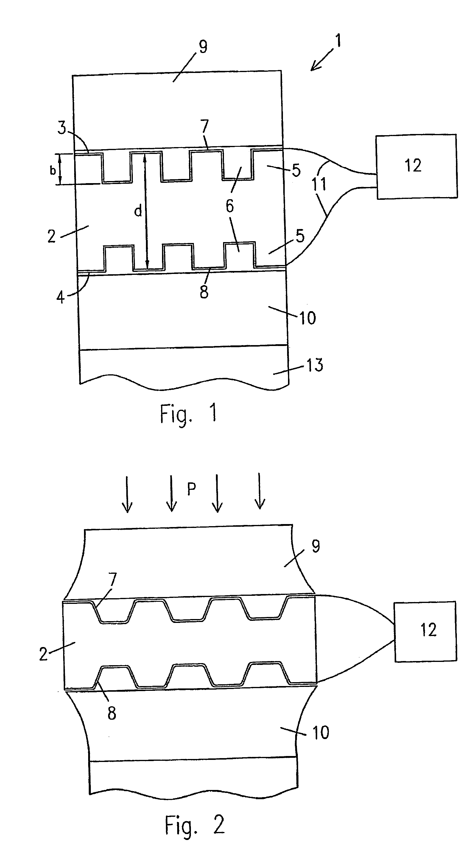
[0026]FIG. 1 shows a tactile sensor element 1 with an elastomeric body 2, preferably made of silicon rubber sheet material. The body has upper and lower surfaces 3 and 4, which have corrugations in the form of parallel ridges and grooves 5 and 6 running across the width of the body in a direction perpendicular to the drawing plane. The ridges and grooves are shown with square profiles, however, other profiles such as sinusoidal or rectangular may be applicable. The depth b of the grooves is typically in the range of 10 to 30% of the total thickness d of the body, which typically is 10 to 50 μm. As an example, the body has a thickness of 20 μm with corrugation depths of 5 μm.

[0027] Metal electrodes 7 and 8 are arranged on both upper and lower surfaces 3 and 4 by deposition of a thin uniform metal layer, such as gold, silver or copper, by use of suitable deposition technique. The electrodes are connected with lead wires 11 to external means 12 for measuring the capacitance of a capac...


PUM


Abstract

A tactile sensor element includes a first pressure transfer layer and a second pressure transfer layer, an elastomeric body arranged between the first and second pressure transfer layers, the body having a first and a second surface opposed to each other, the first and second surfaces having corrugations to allow displacement of elastomeric body material in a predetermined direction perpendicular to the corrugations when exposed to a contact pressure on at least one of the surfaces, a first electrode arranged on the first surface and a second electrode arranged on the second surface, the first and the second electrodes being connectable to external means for determining the capacitance of a capacitor formed by the elastomeric body and the electrodes, where at least one pressure transfer layer has at least one portion of increased thickness. Further disclosed is a tactile sensor array comprising a plurality of sensor elements.

Description

CROSS REFERENCE TO RELATED APPLICATIONS [0001] This application is entitled to the benefit of and incorporates by reference essential subject matter disclosed in international Patent Application No. PCT / DK2003 / 000848 filed on Dec. 10, 2003 and Danish Patent Application No. PA 2002 01908 filed on Dec. 12, 2002. FIELD OF THE INVENTION [0002] The invention relates to a sensor and, more particularly to a tactile sensor element for converting the pressure acting on a surface of a sensor into an electrical signal. BACKGROUND OF THE INVENTION [0003] Tactile sensor and tactile sensor arrays may be used in various applications to provide informations on the magnitude and the local distribution of pressure applied on a given surface area. As examples could be mentioned touch pads or drawing pads for character recognition in computer equipment, or contact pads for the determination and control of grip forces of a robotic gripping tool. [0004] Such sensors widely known are using pressure sensit...

Claims


Application Information

Patent Timeline
IPC IPC(8): G01D7/00G06F3/0354G06F3/044
CPCG06F3/044G06F3/03547G06F3/0447
Inventor GRAVESEN, PETERBENSLIMAND, MOHAMED YAHIA
Owner LEAP TECH APS
Why Eureka
Try Eureka