Saw cutting blade

a cutting blade and saw blade technology, applied in the field of tools, can solve the problems of poor surface quality of the material being cut, and achieve the effects of reducing the size of debris particles, enhancing the removal of debris from the kerf, and sufficient structural strength

Inactive Publication Date: 2006-01-26
ZORICH TIMOTHY A +1
View PDF29 Cites 92 Cited by
  • Summary
  • Abstract
  • Description
  • Claims
  • Application Information

AI Technical Summary

Benefits of technology

[0007] The Aft Body is improved by forming (cutting, perforating, etching or stamping) cutout patterns into the Aft Body either part way or completely through the body which are designed specifically to capture the cut debris, transport it away from the wall of the Kerf, further reduce the size of the debris particles and enhance it's removal from the Kerf. The cutout patterns in the Aft Body are formed as close as practical to the Aft Root Line of the Primary Primary Cutting Edge of the blade while sufficient Aft Body material for maintaining sufficient structural strength and integrity to support the stress and strain encountered by the blade during the cutting operation. The distance is based upon the material of the blade body (steel, aluminum, alloy, ceramic, cermet, etc.) its structural characteristics, the material being cut, the properties of the debris and the characteristics of the motion and force driving the blade. This distance to the leading edge of the cutout pattern will generally range between 1 mm and 25 mm distance from the Aft Root Line of the Primary Cutting Edge, depending on the size of the blade, the body material and the type of material to be cut. A variety of shapes for such cutout patterns will be characterized as examples along with data taken for several different samples demonstrating...

Problems solved by technology

Those particles having a larger size, and those smaller particles that cluster together, rapidly fill the space between the wall of the body of the blade and the cut-wall as the velocity of the blade is increased to its steady state cutting speed, forming a frictional mass of material that generates heat, stress and drag on both the blade and workpiece, c...

Method used


Image

  • Saw cutting blade
  • Saw cutting blade
  • Saw cutting blade

Examples


Embodiment Construction

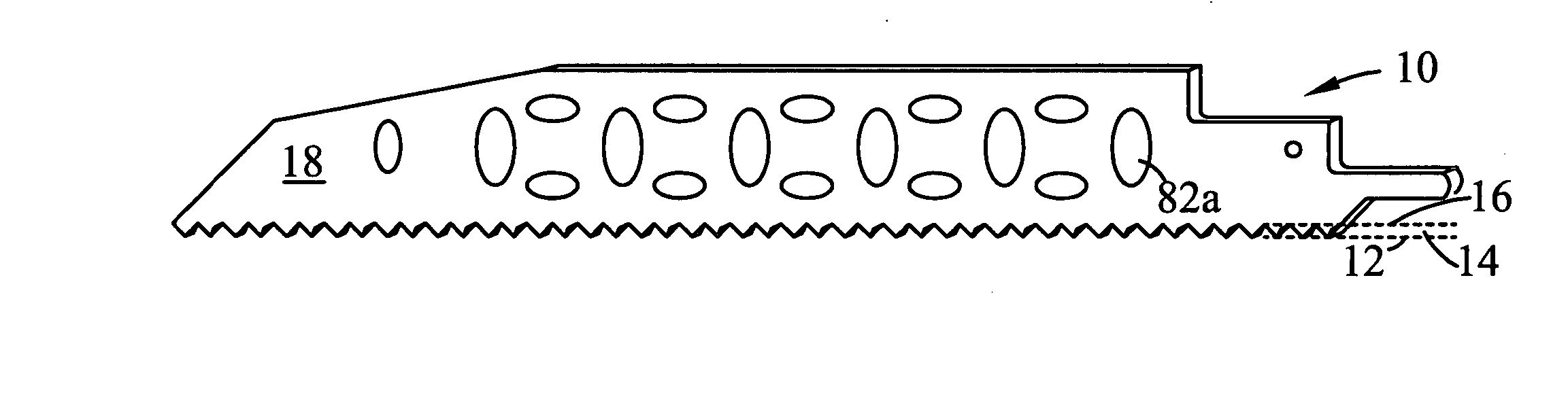
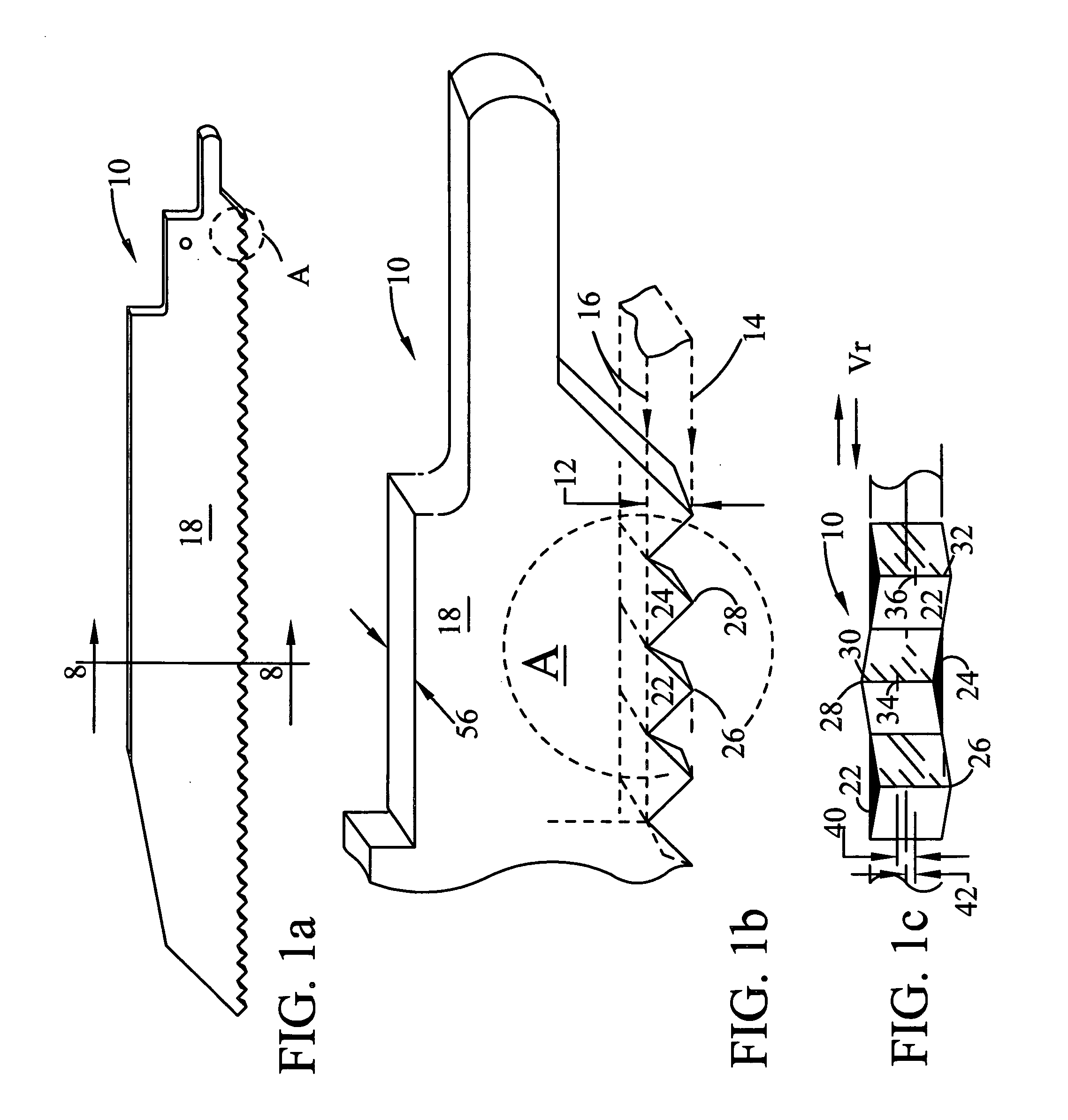
[0046]FIG. 1a. shows a typical reciprocating Saw Blade 10. FIG. 1b shows an expanded region “A” of FIG. 1a that is identified by phantom circle and the letter “A” in each of the views. FIG. 1b is expanded to schematically show several of the saw teeth on the sawblade of FIG. 1a for the purpose of identifying and naming parts of the SawBlade 10 and the saw teeth that are shown with particularity. Saw Blade 10 has a Primary Cutting Edge Region 12 between phantom lines that extend from the Cutting Edge of phantom line 14 to the Aft Root Line or plane identified by phantom line 16. The Primary Cutting Edge Region 12 is at the leading edge of the blade. In addition to the Primary Cutting Edge Region 12, each saw blade has an Aft Body 18 that is integral to and behind the Primary Cutting Edge Region 12, the regions being contiguous along the Aft Root Line 16.

[0047] Early Comments on the Circular Blade

[0048]FIGS. 23 and 24 each show a phantom line 60 that identifies the location of the A...


PUM

PropertyMeasurementUnit
Angleaaaaaaaaaa
Distanceaaaaaaaaaa
Distanceaaaaaaaaaa

Abstract

A saw blade having blade body supporting a leading cutting edge for cutting through a workpiece. A force and motion are applied to drive the cutting edge against the work piece as the body of the saw blade is driven with a reciprocating, rotational or linear motion transverse to the applied direction of the force. The solid rectangular cross section of a saw blade is modified to improve its ability to cut through a workpiece. The body of the blade is characerized as having cut out areas distributed throughout the blade body to capture and remove the debris from the kerf. This improved cutting performance can be further enhanced by reducing the cross section of the body. Secondary cutting edges may also be incorporated around the perimeter of the cutouts and as part of the reduced geometry portion of the blade body.

Description

[0001] This non-provisional patent applicaton claims priority from provisional patent application 60 / 590,795 filed on Jul. 23, 2004 for An Improved Saw Cutting Blade, and having common inventors.BACKGROUND [0002] This invention relates to the field of tools and more particularly to the field of cutting tools and blades for saws. [0003] The cross-sectional side walls of the aft blade body (also referred to as “Aft Body”) which structurally supports the cutting edge of the typical saw blades used with all types of hand saws, reciprocating saws, rotary saws or band saws with motorized drives, exclusive of the cutting edge, generally is solid and has a uniform rectangular cross section. There may also be a few nominal cut out regions, notched regions or indented regions within the walls of the body to act as cooling vents, for stress relief, or to facilitate blade bending when cutting non linear shapes. The cutting edge is typically formed in various type of tooth like geometries with s...

Claims


Application Information

Patent Timeline
IPC IPC(8): B23D47/00
CPCB23D61/123B23D61/025Y10T83/9319Y10T83/9372
Inventor ZORICH, TIMOTHY A.KING, CHAD J.
Owner ZORICH TIMOTHY A
Why Eureka
Try Eureka