Wiring and piping apparatus of part mounting machine

a technology of wiring and piping, which is applied in the direction of insulating conductors, cables, and relatively moving parts, can solve the problems of increasing cost, reducing the service life of cables, and requiring a complex system composed of many constituent parts, so as to improve service life, reduce cost, and simplify the effect of construction

Inactive Publication Date: 2006-01-26
PANASONIC CORP
View PDF10 Cites 10 Cited by
  • Summary
  • Abstract
  • Description
  • Claims
  • Application Information

AI Technical Summary

Benefits of technology

[0012] With this system, the cable is bent in U shape at the midpoint and one end of the cable moves with the guide belt that rotates with the head, while the other end of the cable runs along, and is received by the guide member such that the length of the part of the cable held by the guide member changes in accordance with the rotation of the head. There is no heavy collision between the cable and other parts, nor any excessive stress at fixed parts of the cable, even though the head rotates in both directions at high speed, and so the life of the cable is made longer. The system is thus constructed simple and at low cost, as it only consists of the drive pulley, the driven pulley, the guide belt, and the guide member.
[0020] The above-described system is preferably used for a head that rotates around and moves along the axis, because a change in the distance between the movable guide member and the stationary guide member is smoothly absorbed by a change in the radius of curvature of the U-shaped bent-back portion of the cable, and the above-discussed effects are achieved.

Problems solved by technology

Large and repeated stress applied to fixed parts of the cables and tubes leads to their much shortened life.
Also, the system requires a complex mechanism consisting of many constituent parts.
This leads to increased cost.
Heavy collision between the coiled cord 52 and other objects and excessive stress at the fixed parts lead to a shortened life of the cable.

Method used


Image

  • Wiring and piping apparatus of part mounting machine
  • Wiring and piping apparatus of part mounting machine
  • Wiring and piping apparatus of part mounting machine

Examples


first embodiment

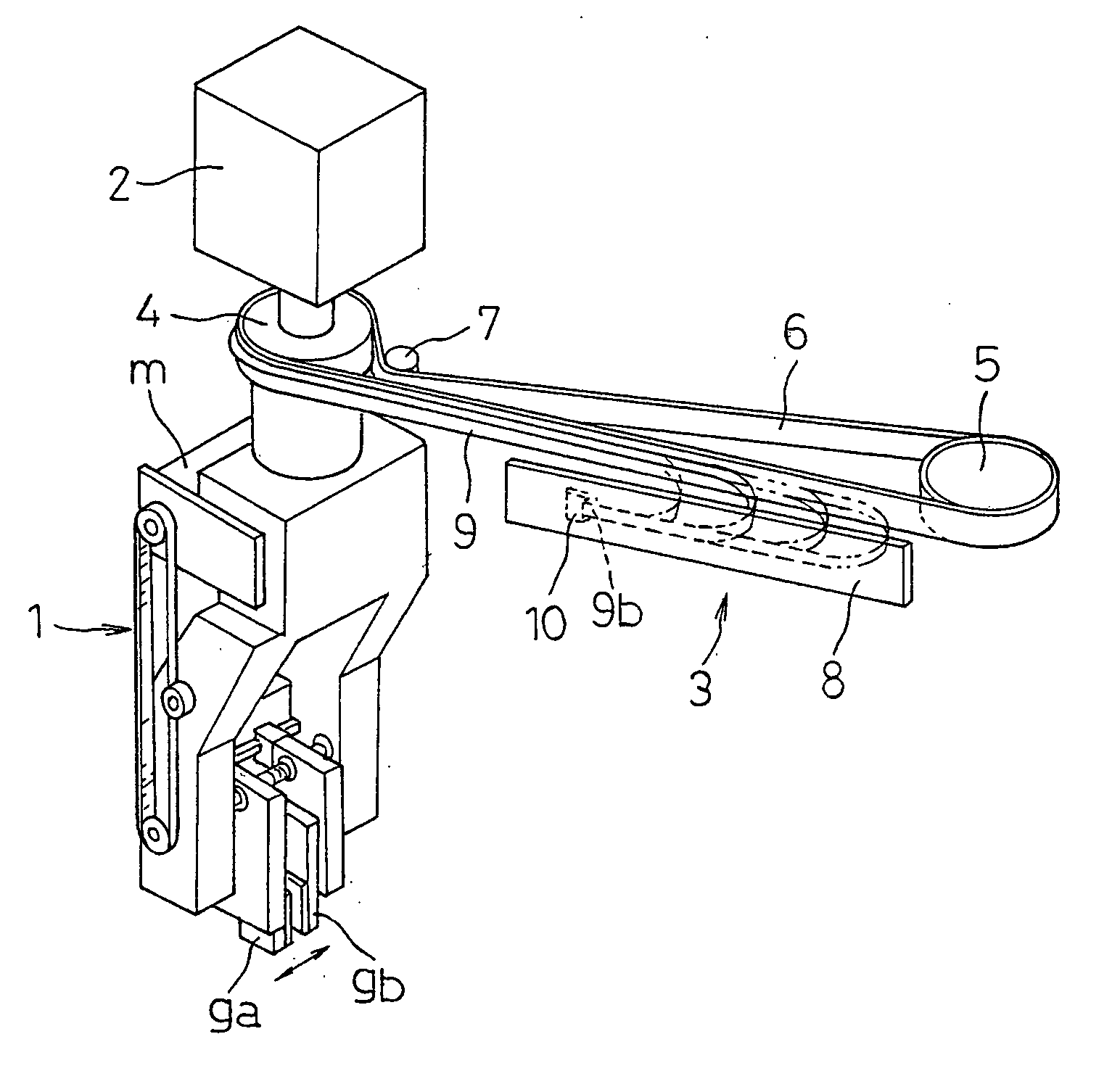
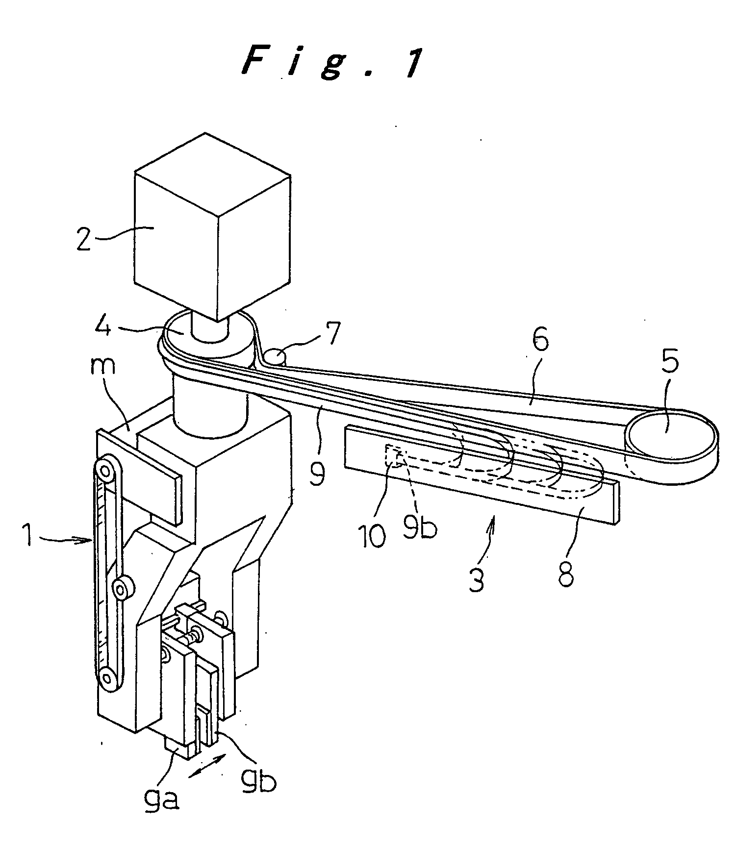
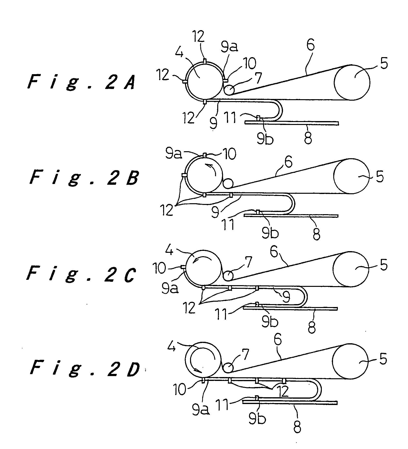
[0032] A first embodiment of a cable / tube installation system for a component mounting apparatus of the invention will be hereinafter described with reference to FIGS. 1, 2A-2D, 9A, and 9B.

[0033] The system of this embodiment is used for connecting cables to insertion heads of component inserters. As shown in FIGS. 9A and 9B, the insertion head 1 holds a component P with its leads 1 bent at right angles such that the leads 1 will be inserted into insertion holes h formed in the circuit board B. The head 1 includes various sensors for detecting the conditions of the component P to be inserted and an encoder for sensing the rotation angle of the insertion head, as well as a drive motor m, as shown in FIG. 1, for moving insertion guides ga and gb in accordance with the pitch distance between the insertion holes h. In addition, the insertion head 1 is designed to be rotatable around its axis with the use of rotating means 2 so that the insertion head 1 will be oriented at 0°, 90°, 180°...

second embodiment

[0039] A second embodiment of a cable / tube installation system for a component mounting apparatus according to the invention will be described hereinafter with reference to FIGS. 3, 4A, and 4B. Incidentally, components of the present embodiment that are similar to those of the previously discussed embodiment will be given the same reference number and only the differences will be described.

[0040] The present embodiment relates to a cable installation system 3 also for use with an insertion head 1 of a component inserter. The system includes a circular pulley 13 that is concentric with the axis of the insertion head 1 and rotates integrally with the head, and a guide member 14 that is located opposite the outer periphery of the pulley 13 with a certain distance. One end 9a of the cable 9 is fixed to the pulley 13. The cable 9 is wound around the pulley 13 from this fixed end, then bent back in U shape and extended along the guide member 14. The other end 9b of the cable 9 is fixed t...

third embodiment

[0043] A third embodiment of a cable / tube installation system for a component mounting apparatus according to the invention will be described hereinafter with reference to FIGS. 5, 6A, and 6B.

[0044] The present embodiment relates to a cable installation system 16 for use with a bending head 15, also referred to as “anvil,” of a component inserter. The bending head 15 rotates in both directions in the angle range of 0 to 90 degrees as indicated by the arrow “a” in FIG. 5, and moves up and down several tens mm along its axis as indicated by the arrow “b.”

[0045] As shown in FIG. 5, the cable installation system 16 for such a bending head 15 includes a movable guide member 17 that is fixed perpendicularly to the axis of the bending head 15, and a stationary guide member 18 placed in parallel with the movable guide member 17. A cable 19 that consists of a plurality of signal lines and power lines arranged side by side is laid in an arc shape as shown in FIG. 6A and bent back in U shape ...


PUM

PropertyMeasurementUnit
rotation angleaaaaaaaaaa
angleaaaaaaaaaa
angleaaaaaaaaaa

Abstract

A guide belt is stretched over a drive pulley that rotates integrally with a head and a driven pulley situated at one side of the drive pulley. One end of the cable is fixedly attached to a part of the guide belt that is always in contact with the drive pulley when the head rotates, while the cable is extended along the guide belt. The cable is bent back in U shape at its midpoint and the cable on the other end side therefrom is extended along a guide member placed substantially in parallel with the guide belt between the drive pulley and the driven pulley. The other end of the cable is fixedly attached to the guide member.

Description

TECHNICAL FIELD [0001] The present invention relates to a cable / tube installation system for use with component mounting apparatuses for connecting cables and tubes to operating heads that rotate in both rotational directions around and / or move along their axis in both directions at high speed, out of various operating heads of such component mounting apparatuses. BACKGROUND ART [0002] In a component mounting apparatus such as a component inserter, as shown in FIG. 9A, an insertion head H receives a component P to be inserted that has leads 1 extending from the axial ends of the component body b and bends the leads 1 in L-shaped angle. The insertion head H then moves to a predetermined position and rotates around its axis such that the tips of the leads 1 are positioned opposite insertion holes h that are formed in a circuit board B in accordance with the mounting position and orientation of the component P to be inserted, and presses down the component body b so that the leads 1 ar...

Claims


Application Information

Patent Timeline
Patent Type & Authority Applications(United States)
IPC IPC(8): H01B7/06H05K13/00H02G11/00H05K13/04
CPCH02G11/00H05K13/0404H02G11/006H05K13/0408H05K13/0413
Inventor YOKOYAMA, DAIMATSUOKA, SATOSHIKOYAMA, TOSHIYUKI
Owner PANASONIC CORP
Why Eureka
Try Eureka