Sky hopper

a technology of vtol and hopper, which is applied in the direction of toy aircraft, vertical landing/take-off aircraft, aircraft navigation control, etc., can solve the problems of limited use of helicopters, limited use of internal combustion engines, and numerous constraints of current travel methods, and achieve the effect of enhancing the shaft power produced by internal combustion engines

Inactive Publication Date: 2006-01-26
PAK STEVE
View PDF39 Cites 177 Cited by
  • Summary
  • Abstract
  • Description
  • Claims
  • Application Information

AI Technical Summary

Benefits of technology

[0012] The present invention in a preferred embodiment further comprises a fan cooling radiator thermally connected above the internal combustion engine for providing forced convection heat transfer to the internal combustion engine. The aircraft additionally comprises a supercharger mechanically connected to the internal combustion engine for enhancing the shaft power produced by the internal combustion engine.

Problems solved by technology

Current methods of travel have numerous constraints, particularly conventional air travel that requires expensive airports having long runways and vast airspace.
For many reasons, however, the helicopter has remained a limited-use, special-purpose aircraft.
Principally, the large rotating lift blades of the helicopter design must meet very stringent mechanical requirements and require a very complicated system for drive and control.
Another disadvantage of the helicopter is that the angular moment caused by the lift blades requires the use of a tail rotor rotating about a horizontal axis.
Loss of the tail rotor is thus a potentially devastating casualty.
Helicopters also employ pitch adjustable blades resulting in extremely expensive construction and maintenance costs and a high level of pilot proficiency in flying and controlling the aircraft.
While this design is capable of supersonic speeds, an aircraft of this system will be very heavy and require a relatively powerful vertical thrust.
This design will also yield a relatively heavy aircraft as it employs multiple engines with large horsepower requirements.
Furthermore, mobility and maneuverability are concerns especially at lower air speeds and transitioning between hovering and normal flight mode.
These designs however will be relatively heavy and will not have a particularly attractive power-to-weight ratio.
Also, in vertical flight mode, a large weight proportioned at a distance from the aircraft's center of gravity will cause a moment of inertia adversely affecting stability and mobility.

Method used


Image

  • Sky hopper
  • Sky hopper
  • Sky hopper

Examples


embodiment 500

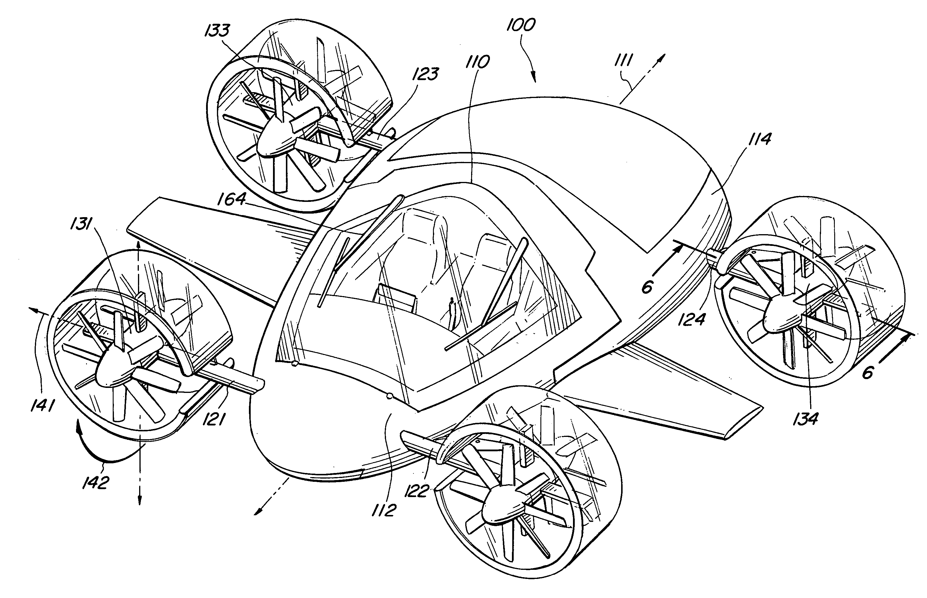
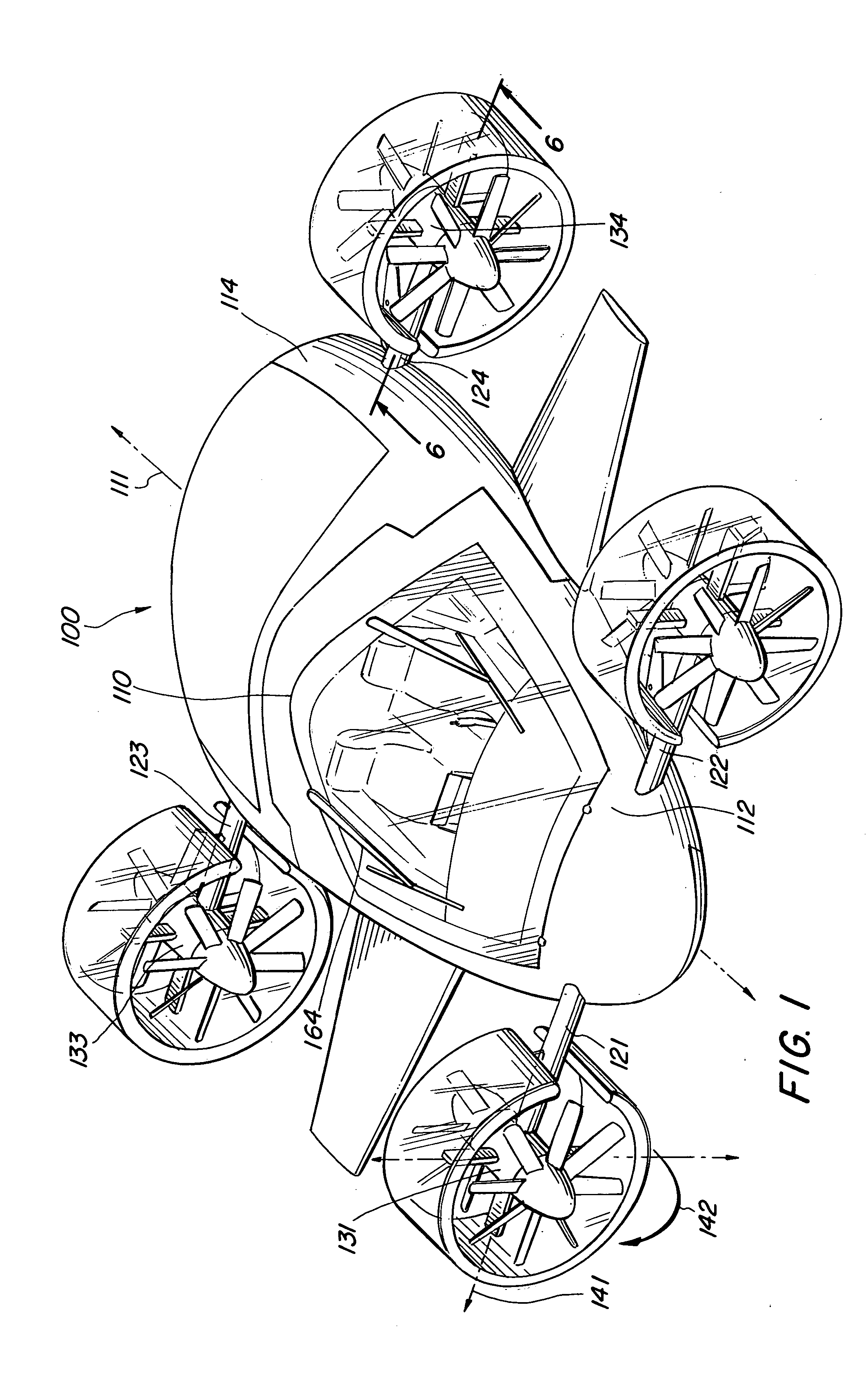
[0047]FIG. 4 illustrates a bottom aspect isometric view of the preferred VTOL aircraft 100 illustrating exterior features. Airbrake 299 has deployed and stowed positions and is being illustrated in its stowed position. FIGS. 5A and 5B illustrate a second preferred embodiment 500 of the present invention in flight and landed modes, respectively. This embodiment 500 employs airbrakes 510, 520 on right and left sides of the aircraft 500 and does not included control surfaces 151, 152. FIG. 5B also shows landed aircraft 500 having rudders 540 (FIGS. 7A and 7B) that vector thrust or impart a moment on the aircraft 500 and provide directional control of the aircraft 500 during flight.

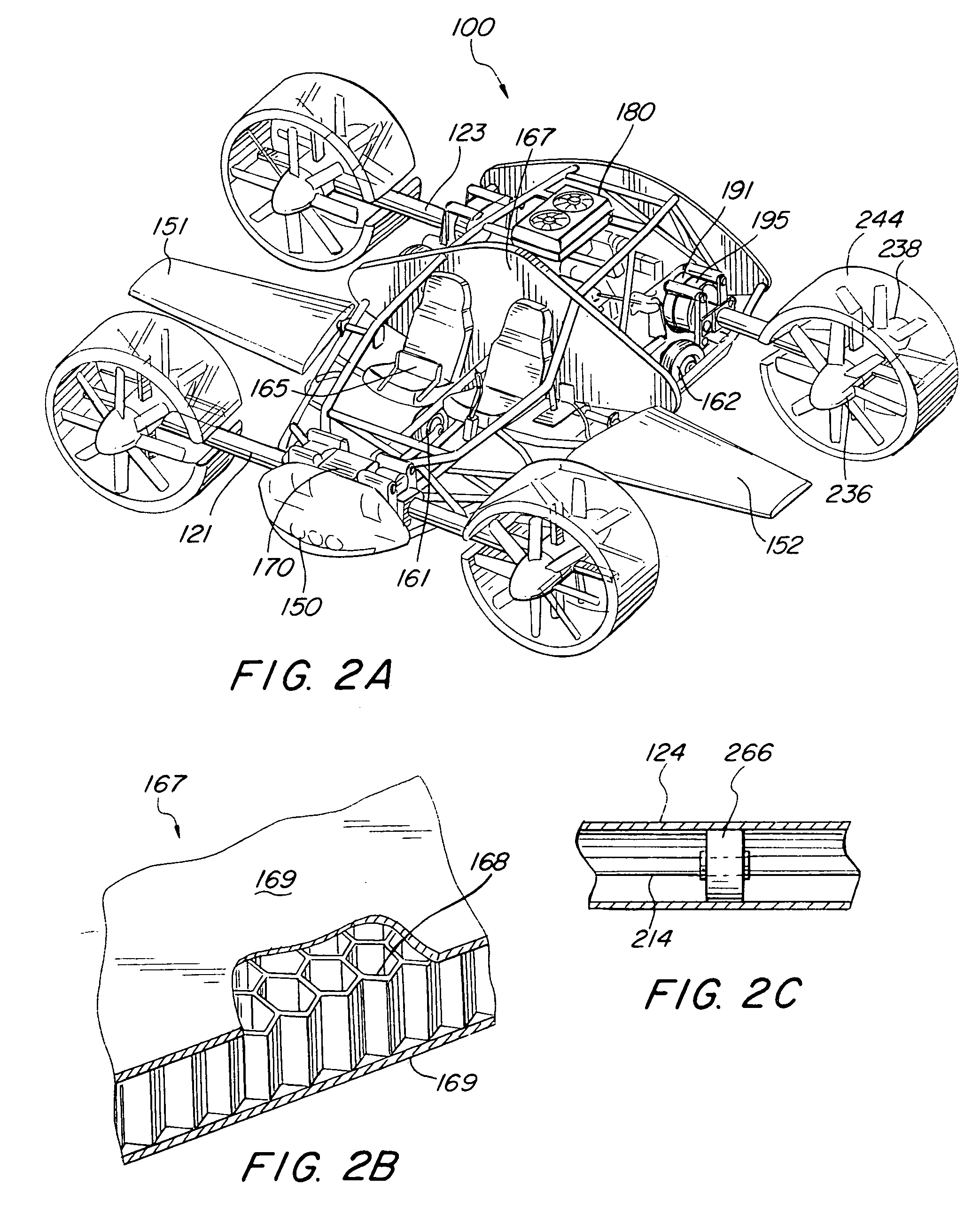
[0048] Referring to FIG. 6 a perspective view of a first preferred propulsion unit 134 has been sectioned along line 6-6 of and is illustrated in FIG. 1. Initially, shaft power is transferred from horizontal shaft 214 to forward (not shown) 236 and rear fan units 238, via planetary gear assembly 176. Shaft 21...

embodiment 600

[0052]FIG. 9A is an additional illustration of power train 200, generally as viewed from a forward position and FIG. 9B illustrates an alternative power train 600 of the present invention. Power train 600 instead employs four electric motors 611, 612, 613, 614 providing shaft horsepower, the motors 611, 612, 613, 614 receive electrical power from power generator 610. It is contemplated that generator 610 will require relatively high electrical output requirements without adding significant size and weight, and the required shaft horsepower may require three-phase electrical power with single-phase or three-phase motors. This embodiment 600 may be referred to as a “hybrid configuration.”

[0053]FIGS. 10A through 10H illustrate a preferred VTOL aircraft 700 in various operational modes. This particular embodiment 700 has control surfaces 151, 152 and rudders, 540 for example, for directional control. FIG. 10A shows aircraft 700 in park with landing gear 161, 162 deployed. FIG. 10B shows...


PUM


Abstract

A vertical takeoff and landing (VTOL) aircraft design particularly suitable as a full-sized aircraft or remote controlled (RC) model aircraft is disclosed. The invention employs lightweight, high strength materials to reduce the power requirements of the propulsion plant. A preferred system of the invention comprises one internal combustion engine able to spit shaft power to four fan units. The fan units further employ counter rotating fan blades for stability. Separate horizontal and vertical tilting mechanisms delivered to the fan units are additionally disclosed. A variation in design is further included wherein electric motors provide the necessary shaft power.

Description

BACKGROUND OF THE INVENTION [0001] 1. Field of the Invention [0002] The present invention pertains generally to vertical takeoff and landing (VTOL) aircraft. More particularly, the present invention pertains to aircraft having tilting propulsion systems for vertical takeoff. The present invention is particularly, but not exclusively, useful as a VTOL aircraft design for relatively small remote control (RC) aircraft and larger passenger aircraft. [0003] 2. Description of the Prior Art [0004] Vertical Takeoff and Landing (VTOL) aircraft are generally any of numerous unconventional designs for aircraft including rotary wing helicopters, having rotatable or divertible propulsion systems that allow for vertical takeoff / landing and horizontal flight. Advancements in technology have long been desired to produce a more commercially viable design for VTOL aircraft. Current methods of travel have numerous constraints, particularly conventional air travel that requires expensive airports havin...

Claims


Application Information

Patent Timeline
Patent Type & Authority Applications(United States)
IPC IPC(8): B64C29/00
CPCA63H27/14B64D35/04B64C29/0033
Inventor PAK, STEVE
Owner PAK STEVE
Why Eureka
Try Eureka