
Method of cooling gas turbine blades

A technology for gas turbine blades and turbine blades, which is applied in the direction of blade support components, mechanical equipment, engine components, etc., can solve the problems of weak lifting effect of cooling turbine blades, reducing the heat capacity of cooling gas, and affecting the performance of gas turbines. The effect of simplifying the structure, increasing the shaft power and improving the service life

Active Publication Date: 2015-10-28
马重芳 +2
View PDF6 Cites 0 Cited by
  • Summary
  • Abstract
  • Description
  • Claims
  • Application Information

AI Technical Summary

Problems solved by technology

With the further increase of the turbine gas inlet temperature, the improvement effect of relying on compressed air to cool the turbine blades becomes weaker and weaker. On the one hand, due to the increase in heat, the amount of air used to cool the turbine blades has reached 20% of the total amount of compressed air. or higher, resulting in a large amount of power consumption and seriously affecting the performance of the gas turbine; It is more difficult to cool down

Method used


Image

  • Method of cooling gas turbine blades
  • Method of cooling gas turbine blades
  • Method of cooling gas turbine blades

Examples


Embodiment Construction

[0021] The principle, specific implementation and working process of the present invention will be further described below in conjunction with the accompanying drawings.

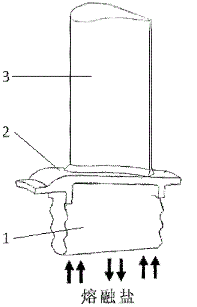
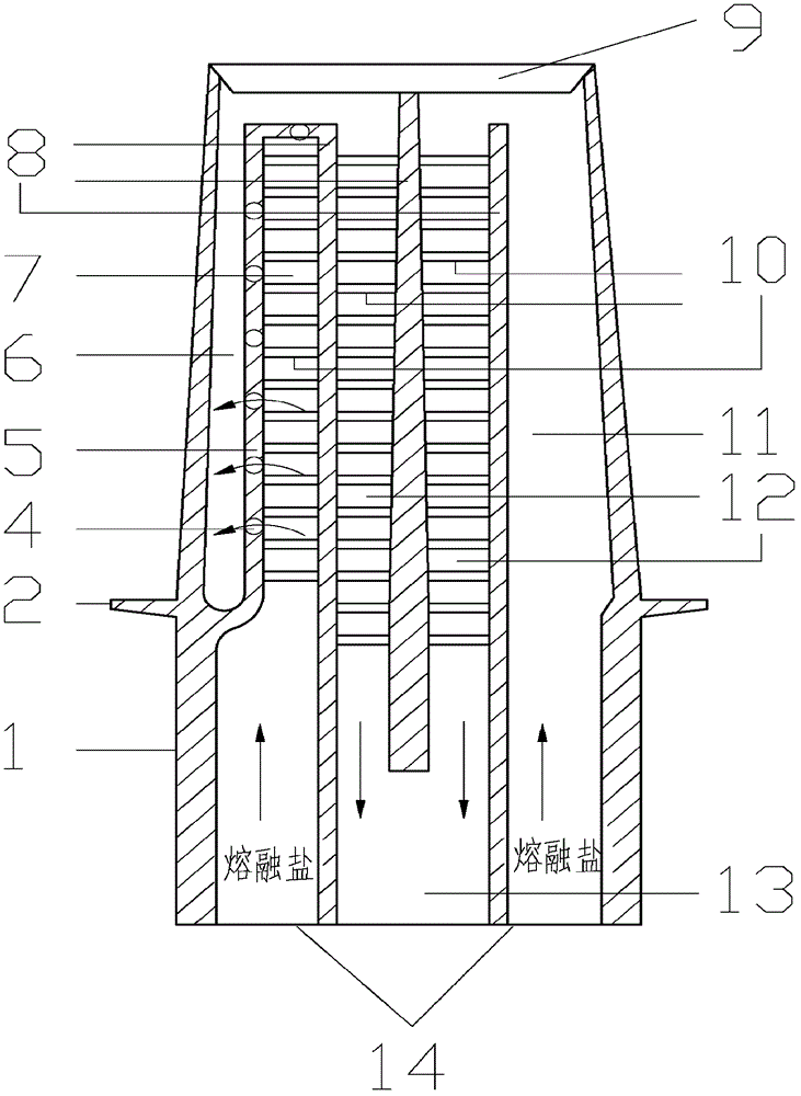
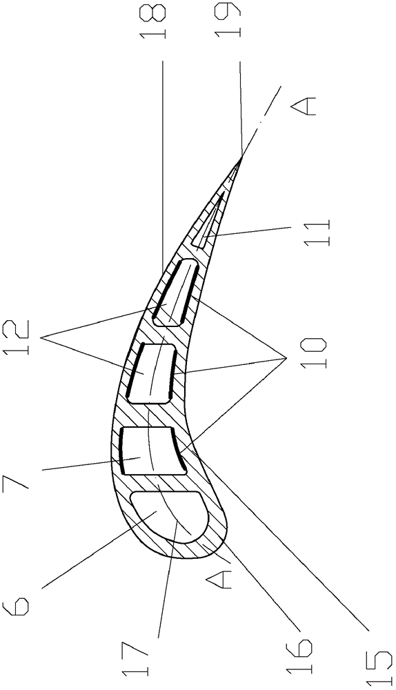
[0022] Accompanying drawing has provided a specific embodiment of the present invention, figure 1 It is a three-dimensional view of a high-temperature turbine blade of a gas turbine, which includes a blade profile 3, a blade heel 1, and a blade platform 2 connecting the two. Cutting the blade along the central arc 17 of the blade, the internal structure of the blade can be obtained such as figure 2 shown. There are multiple cooling passages 6, 7, 11, 12 for cooling the flow of molten salt inside the blade, and molten salt (such as mixed molten salt composed of 40% potassium nitrate and 60% sodium nitrate by mass percentage) is fed by the blade root cooling passage inlet 14 It enters the internal cooling passages 6 and 11 of the blade, flows through the internal cooling passages 7 and 12 respectively, and ...


PUM


Abstract

The invention relates to a method for cooling a combustion gas turbine blade. According to the method, molten salts are used as cooling working media, the bran-new blade internal passage cooling is designed, and the air film cooling is not utilized. The front edge of the blade is cooled by utilizing jet impingement holes and a turbulence reinforcing device arranged in a cooling passage, and other positions of the blade are cooled by a blade internal passage. After entering a blade cavity, the molten salts flow through the blade cavity along a cooling passage, the pressure surface and the suction surface of the blade and the tail edge of the blade are cooled in one step, partial molten salts form jet flows at the front edge of the blade for realizing the impingement cooling, then, the molten salts are discharged from a cooling passage outlet formed at the root part of the blade, a sealed U-shaped cooling loop is formed, and the cooling of the whole blade is completed. The cooling method has the advantages the temperature of the turbine blade can be maintained to be within 600 DEG C, in addition, compressed air is not consumed, the internal structure of the blade is greatly simplified, the processing process and the material requirements of the blade are reduced, the intensity of the blade is enhanced, the service life of the blade is prolonged, the manufacturing cost of a combustion gas turbine is obviously reduced, and the shaft work power of the combustion gas turbine is improved.

Description

technical field [0001] The invention relates to a cooling medium, a cooling method and a cooling structure of a gas turbine blade. Background technique [0002] Gas turbines are the core components in the field of energy equipment, and play an important role in military and industrial fields such as aviation, ships, and land. With the continuous increase of the inlet gas temperature of advanced gas turbine turbines, more stringent challenges have been imposed on the manufacturing process and cooling requirements of high-temperature turbine components. At present, the inlet gas temperature of advanced gas turbine turbines has exceeded 1500 °C, and is further moving towards 1900 °C and even Higher temperature, while the current working temperature of advanced nickel-based alloys is below 1100°C, in order to ensure the life of high-temperature turbine blades, it is necessary to use strong cooling methods to keep the overall temperature field and stress distribution of the blade...

Claims


Application Information

Patent Timeline
Patent Type & Authority Patents(China)
IPC IPC(8): F01D5/18
Inventor 马重芳吴玉庭刘斌任楠张业强熊亚选陈永昌
Owner 马重芳
Learn More