Equine hoof pad for break over modification

Inactive Publication Date: 2006-02-02
OVNICEK EUGENE D +1
View PDF17 Cites 13 Cited by
  • Summary
  • Abstract
  • Description
  • Claims
  • Application Information

AI Technical Summary

Benefits of technology

[0008] A further object of the invention is to provide apparatus that will permit a wide range of break

Problems solved by technology

If the laminae are inflamed or already stretched or torn, the force produced on the toe of the hoof at break over increases the strain on the laminae, the attaching lig

Method used


Image

  • Equine hoof pad for break over modification
  • Equine hoof pad for break over modification
  • Equine hoof pad for break over modification

Examples


Embodiment Construction

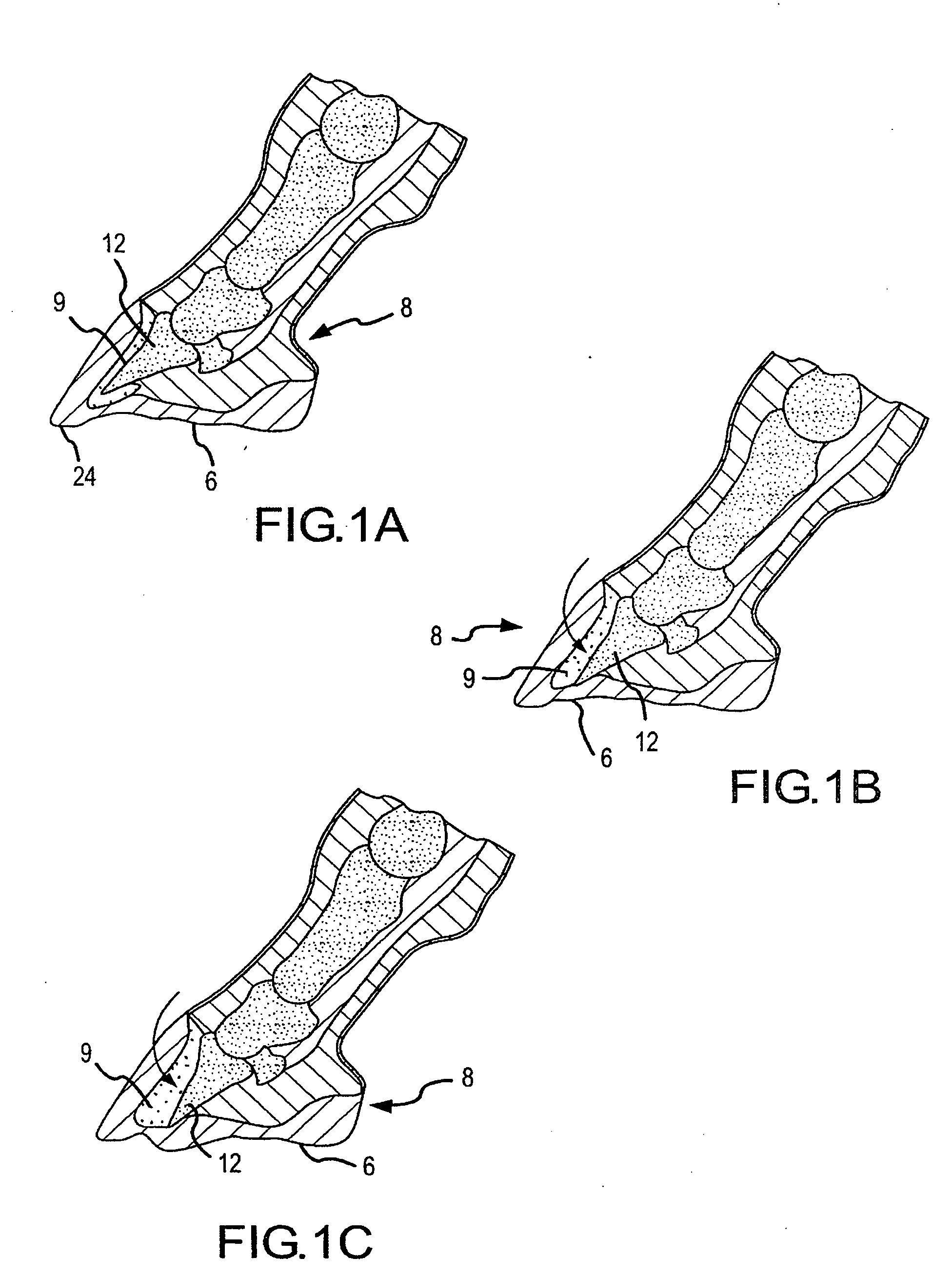
[0030]FIGS. 1a-1c respectively illustrate in diagrammatic form three typical states or phases of equine laminitis, mild, moderate and severe. In each case the coffin bone 12 of the horse's hoof 8 has prolapsed out of its normal position as a result of the partial or complete failure of the interdigitated laminae 9. As earlier stated, laminitis is it not the only pathology treatable with the apparatus and method of the present invention, however the accompanying drawings and this description will focus on laminitis to best explain the present invention.

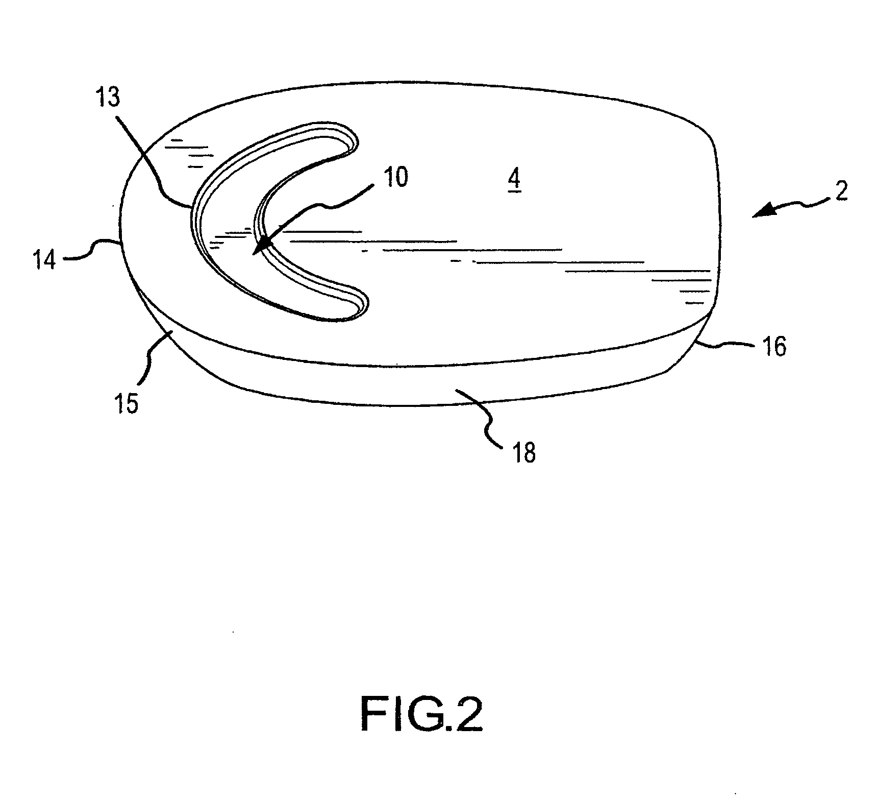
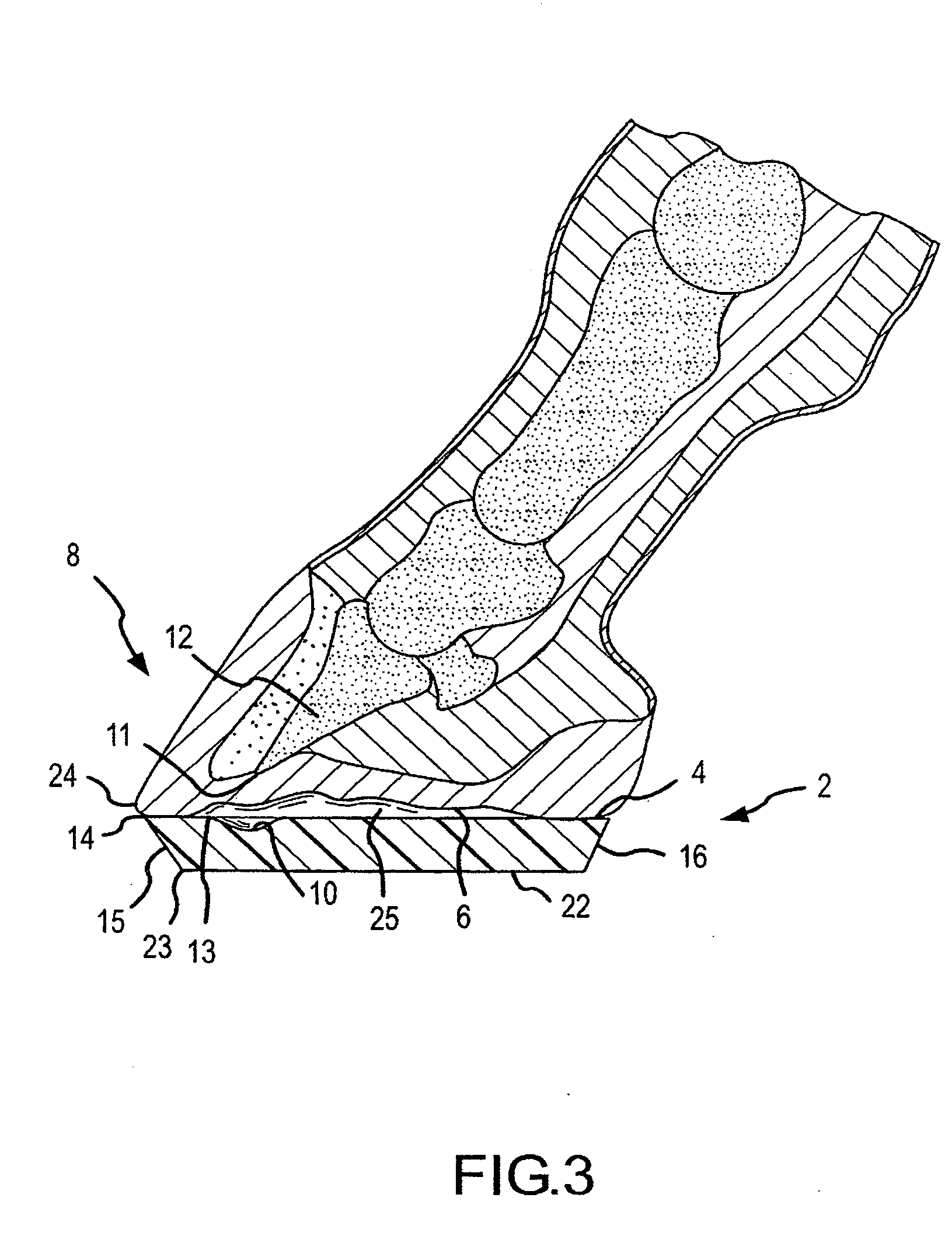
[0031] The primary pad 2 of the present invention is shown in FIG. 2. The pad comprises a block of rigid material having a flat upper surface 4 intended for mounting against the bottom ground-contacting surface 6 of the horse's hoof 8, as seen in FIG. 3. The forward portion of the flat upper surface 4 is relieved to form a trough 10 that is crescent shaped, similar to the peripheral distal border 11 of the coffin bone 12, and having a...


PUM


Abstract

A hoof pad for treatment of equine lower limb pathology comprising, a pad formed of rigid material having an upper hoof contacting surface spaced apart from a lower flat surface that is adapted for ground contact or for mounting of a supplemental pad, the anterior, posterior, medial and lateral side surfaces being sloped and curvilinearly interconnected and where the anterior and posterior side surfaces have a lesser slope than the medial and lateral side surfaces, said pad having a plan view shape substantially similar to that of the ground contacting surface of a horse's hoof, but laterally wider.

Description

FIELD OF THE INVENTION [0001] The present invention relates to equine hoof appliances primarily intended for animals afflicted with lameness but which can be useful for sound horses in some disciplines. BACKGROUND OF THE INVENTION [0002] Equine lameness can be caused by a large variety of lower limb pathologies. Laminitis, ringbone and navicular inflammation are among the most common, all of which will favorably respond to a restriction of movement of the distal phalanges joints, as is achieved by the apparatus and method of the present invention. The present invention will be best explained by reference to its use in the exemplar treatment of one particular pathology, laminitis. [0003] Basically, laminitis is an inflammation of the laminae in a horse's hoof caused by a number of different factors, including grain overload, steroid therapy, retained placenta, colic, toxins, generalized disease and others. More specifically, laminitis is a common, painful, and potentially disastrous ...

Claims


Application Information

Patent Timeline
IPC IPC(8): A01L3/00
CPCA01L7/02
Inventor OVNICEK, EUGENE D.STEWARD, MICHEAL L.
Owner OVNICEK EUGENE D
Why Eureka
Try Eureka