Ozone retention method and system

a technology of ozone retention and ballast water, which is applied in the direction of special purpose vessels, vessel construction, and the nature of treatment water, etc., can solve the problems of unpredictable disinfectant treatment, damage to the water environment, and non-indigenous discharged species, etc., to achieve cost saving, cost effective, and effective effect of direct injection equipmen

Inactive Publication Date: 2006-02-02
NUTECH O3 INC
View PDF37 Cites 22 Cited by
  • Summary
  • Abstract
  • Description
  • Claims
  • Application Information

AI Technical Summary

Benefits of technology

[0013] And another embodiment is a ballast-water treatment system comprising: a vessel including at least one ballast tank; an ozone generator that generates ozone; a ballast water conduit that transports water from a first intake location to a discharge location of a vessel; a bypass line from a first point of the water conduit to a second, return point to divert a portion of the water from the conduit for circulation in the bypass line and back to the water conduit at the return point; and an injector to inject ozone into the diverted portion of water and interposed in the bypass line at a location to provide a determined retention time period between a point of ozone injection and a point of recombining the injected portion with the water charging to the ballast tank.

Problems solved by technology

The discharged species may be nonindigenous and deleterious to the discharge water environment.
The nonindigenous species may cause damage to the water environment and replace benthic organisms and clear plankton communities that provide food and larvae for desirable resident native species.
The complexity and variation of the water makes disinfectant treatment unpredictable.
Various known methods and systems for treating water may not work for treating ballast water because of a resistant life form or unexpected chemical constituency or a proposed treatment itself may degrade an environment upon discharge.
However direct tank sparging may make ozonation disinfection expensive and ineffective as not all spaces in ballast tanks may be reached.
While in-line ozonation of seawater during pumping intake or discharge is more effective and more economical than in-tank treatment, in some instances there are serious cost restrictions on direct ozonation.
The cost of equipment for direct injection into this size line is prohibitive.
There is a need for an uncomplicated and cost effective system and method for direct ozonation of intake / discharge ballast water.

Method used


Image

  • Ozone retention method and system
  • Ozone retention method and system
  • Ozone retention method and system

Examples


example i

[0049] In this EXAMPLE, ballast water is fed from an intake / discharge conduit between a sea chest and a battery of ballast tanks of a 100,000 to 150,000 DWT tanker. The water is fed at a 10,000 gpm flow rate. The seawater contains 70 mg / L of bromide.

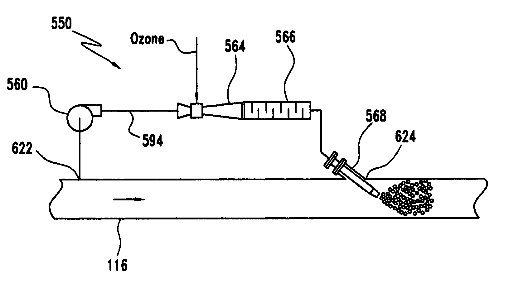
[0050] A bypass stream of water is diverted from the intake / discharge conduit at a constant flow into a bypass conduit system illustrated in FIG. 5. Ozone gas is fed under slight pressure (12-15 psi) from its generating source through 316L stainless steel piping to a venturi injector. The ozone is injected as a 10-12% ozone in oxygen admixture. A bypass flow rate is set to permit effective injection by the venturi. In this EXAMPLE, a bypass flow rate is set at 66 gpm and pressure of approximately 90 psi. This flow rate is 0.3% of the main flow for every mg / L of ozone to be dosed (2.0 mg / L in this EXAMPLE). Flow and pressure are maintained by a positive displacement pump.

[0051] The selected flow rate and pressure are confirmed as follow...

example ii

[0053] In this EXAMPLE, bypass piping length for the bypass 594 is limited and a higher than typical pumping rate is maintained to reduce retention time down to almost 0.2 seconds as follows:

[0054] A bypass flow rate of 66 gpm typically requires a 2″ pipe size. In this EXAMPLE, a smaller pipe size is selected to improve the flow velocity. Since back pressure on the venturi is also a limitation, the selected pipe size is decreased by only one size increment, i.e. to 1½″. The cross-sectional area of a 1½″ Schedule 80 pipe is 0.01227 square feet. The flow rate is (66 / (7.48×60))=0.1471 ft3 / sec, so that the velocity in the pipe is increased to 0.1471 / 0.01227=12 ft / sec.

[0055] The bypass system is designed to provide a minimum length (retention length) from venturi to main conduit reinjection point as follows. The retention length is limited to a first 15 nominal diameters length to accommodate a static mixer and an additional 30 inches to accommodate an angled reinjector. The retention ...


PUM

PropertyMeasurementUnit
molar ratioaaaaaaaaaa
retention timeaaaaaaaaaa

Abstract

A method and system of ozone treatment diverts a portion of water from a flow of water in a conduit, injects ozone into the portion to provide an ozonated portion, and recombines the ozonated portion with the flow of water in the conduit. Another method and system identifies a species-destructive reaction product of ozone with a water constituent, determines a life of the reaction product, and contacts ozone with a water containing the species for a period determined according to the determined life of the reaction product.

Description

[0001] This application in a continuation-in-part application of copending U.S. Application Ser. No. 11 / 039,819, filed Jan. 24, 2005, which in turn is a continuation-in-part of copending U.S. application Ser. No. 10 / 402,298, filed Mar. 31, 2003, now U.S. Pat. No. 6,869,540, which claims the benefit of U.S. Provisional Application Ser. No. 60 / 372,806, filed Apr. 17, 2002, all the disclosures of which are incorporated herein by reference in their entirety.BACKGROUND OF THE INVENTION [0002] The invention relates to a ballast water ozone injection method and system. More particularly, the invention relates to a system for injecting ozone to treat water during loading or discharge to or from the ballast tanks of a vessel or ship. [0003] Ballast water weight is used by sea vessels to compensate for a lack of cargo weight when the cargo load is empty or partially empty in order to maintain the ship's stability For example in a typical transport operation, a vessel docks at a first port whe...

Claims


Application Information

Patent Timeline
Patent Type & Authority Applications(United States)
IPC IPC(8): C02F1/78B63B13/00C01B13/10C02F1/00
CPCB63B13/00B63J4/002C01B13/10C02F1/766C02F2301/046C02F2103/008C02F2201/782C02F2209/005C02F2209/40C02F1/78Y10S210/931
Inventor LEEUWEN, JOHANNES VANJENNINGS, MICHAEL D.MUELLER, RICHARD A.ROBINSON, JACK H.
Owner NUTECH O3 INC
Why Eureka
Try Eureka