Glass substrate having a grooved portion, method for fabricating the same, and press mold for fabricating the glass substrate

a technology of glass substrate and groove, which is applied in the field of glass substrate, can solve the problems of insufficient flow control, difficult handling, and one of the tops being likely to be chipped when contacting another member, so as to prevent the boundary portion from being chipped, prevent the damage of an optical fiber, and facilitate the fabrication of the substrate

Inactive Publication Date: 2006-02-02
ASAHI GLASS CO LTD
View PDF2 Cites 3 Cited by
  • Summary
  • Abstract
  • Description
  • Claims
  • Application Information

AI Technical Summary

Benefits of technology

[0046] According to the mode defined in item 12), the boundary portion between adjacent surfaces of each of the cut-out portions is arcuately chamfered. Accordingly, it is possible to prevent the boundary portion from being chipped and to prevent an optical fiber from being damaged by a chipped portion of the boundary portion.
[0047] In accordance with the method for fabricating an optical fiber fixing substrate according to the mode defined in item 13), the optical fiber fixing substrate is fabricated in a single pressing step, being subjected to heat and pressures by the mold member, which has the concave and convex portion for forming the grooved portion, the concave portions for forming the bonding projection, and the convex portions for forming the cut-out portions, wherein the concave and convex portion and the concave portions are formed in the indented portion surrounded by the entire periphery of the mold reference surface forming flat surfaces of the convex portions. Accordingly, it is possible to establish mass production since it is possible to fabricate the substrate more easily in comparison with the method for fabricating an optical fiber fixing substrate by etching, and the method for fabricating an optical fiber fixing substrate by pressing, followed by grinding.

Problems solved by technology

Since there is a possibility that any one of the other portions is inadvertently chipped to damage an optical fiber, there is a problem that handling is difficult.
Since the optical fiber fixing substrate disclosed in JP-A-11-194226 has only the tops of the V-shaped grooves chamfered, there is another problem that any one of the tops is likely to be chipped when contacting another member.
Such a micro-reactor chip or such a substrate for microanalysis has a flat portion formed with grooves in microns for flowing a solution and has a problem that trouble is caused in reaction or analysis when a groove is chipped.
Although a cover, such as a glass sheet in a flat shape, is put over the grooves for forming flow passages, there is a possibility that a flow rate fails to be sufficiently controlled unless the flat portion in addition to the shape of the grooves has necessary molding precision.

Method used


Image

  • Glass substrate having a grooved portion, method for fabricating the same, and press mold for fabricating the glass substrate
  • Glass substrate having a grooved portion, method for fabricating the same, and press mold for fabricating the glass substrate
  • Glass substrate having a grooved portion, method for fabricating the same, and press mold for fabricating the glass substrate

Examples


Embodiment Construction

[0056] Preferred embodiments of the substrate with a grooved portion, the method for preparing the same and the press mold for fabricating the glass substrate, according to the present invention will be described in reference to the accompanying drawings.

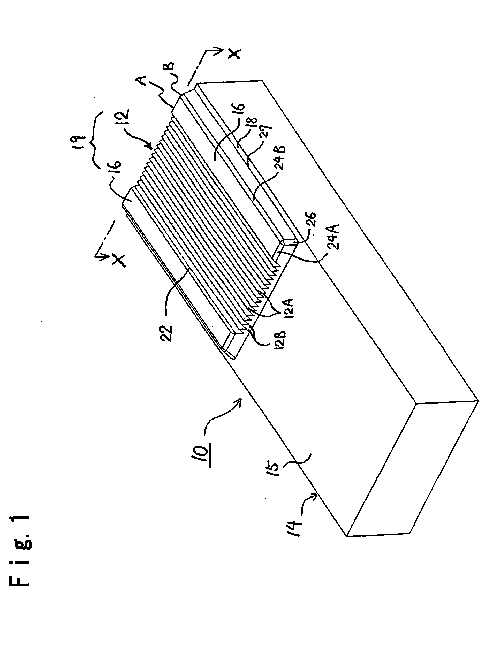
[0057] An optical fiber fixing substrate 10 as shown in FIG. 1 is configured in a substantially rectangular parallelepiped shape and has a flat portion formed with a V-shape grooved portion (grooved portion) 12 for bonding and fixing end portions of a bundle of optical fibers.

[0058] The V-shape grooved portion 12 is configured so as to have peaks 12A and valleys 12B alternatively formed therein. An example of the optical fibers bonded and fixed to valleys 12B is an optical fiber comprising a core and a clad, and having a diameter of about 130 μm. Such optical fibers are bonded and fixed to the V-shaped grooved portion 12 so as to be arrayed at equal distances on the optical fiber fixing substrate 10, V-shaped grooves being fabrica...


PUM

PropertyMeasurementUnit
diameteraaaaaaaaaa
groove depthaaaaaaaaaa

Abstract

A press mold for fabricating a glass substrate, the glass substrate comprising a substrate; and a terrace-shaped flat portion formed on the substrate and having a grooved portion formed therein, is characterized in that the press mold comprises a top mold and a bottom mold; at least one of the top mold and the bottom mold having an indented portion formed therein so as to correspond to the terrace-shaped flat portion, the indented portion having an entire periphery surrounded by a mold reference surface.

Description

BACKGROUND OF THE INVENTION [0001] 1. Field of the Invention [0002] The present invention relates to a glass substrate including a grooved portion formed in a micron structure in a terrace-shaped flat portion formed on a substrate, such as a micro-reactor chip, a substrate for microanalysis or an optical fiber fixing substrate, a method for fabricating the same, and a press mold for fabricating the glass substrate. [0003] 2. Discussion of Related Art [0004] In the field of optical communication, there has been known an optical fiber fixing substrate, which brings opposed end portions of optical fibers into alignment with each other and fixes both opposed end portions for connection of plural optical fibers or plural optical fibers and other elements, such as light guides (for example, JP-A-11-194226, pages 5 and 6, FIG. 1 and FIG. 4). [0005] This optical fiber fixing substrate includes an optical fiber engaging portion having V-shaped grooves formed therein to engage (put) opposed e...

Claims


Application Information

Patent Timeline
Patent Type & Authority Applications(United States)
IPC IPC(8): H01L23/48C03B11/08G01N35/00G02B6/36
CPCC03B11/082C03B2215/413G02B6/3696G02B6/3636G02B6/3652G01N2035/00158
Inventor SHIMAZAKI, TAKESHIOHYAMA, MASATOSHIWAKATSUKI, HIROSHI
Owner ASAHI GLASS CO LTD
Why Eureka
Try Eureka