
Square wave drive system

a drive system and square wave technology, applied in the direction of instruments, light sources, electrical equipment, etc., can solve the problem of limited power required to generate ligh

Inactive Publication Date: 2006-02-02
BANK OF AMERICA NAT TRUST & SAVINGS ASSOC
View PDF46 Cites 54 Cited by
  • Summary
  • Abstract
  • Description
  • Claims
  • Application Information

AI Technical Summary

Benefits of technology

[0010] One embodiment of the present invention is a power conversion circuit that improves lamp operating life and lamp efficiency by driving a fluorescent lamp with a square wave signal (or a rectangular wave signal). The square wave signal is an AC signal with relatively fast transition times (e.g., fast rise or fall times). For example, the transition times for a 50 kilohertz square wave signal may be in the range of one to two microseconds. In one embodiment, the transition times are less than one-twentieth of a period of the square wave signal.
[0011] A square wave signal advantageously reduces lamp current crest factor for more efficient operation of a fluorescent lamp. For example, a lamp current crest factor associated with a square wave voltage provided to a fluorescent lamp can be in the range of 1.0 to 1.2. In one embodiment, the lamp efficiency improves by more than 20% when a square wave signal, rather than a sinusoidal signal, is provided to drive the fluorescent lamp.
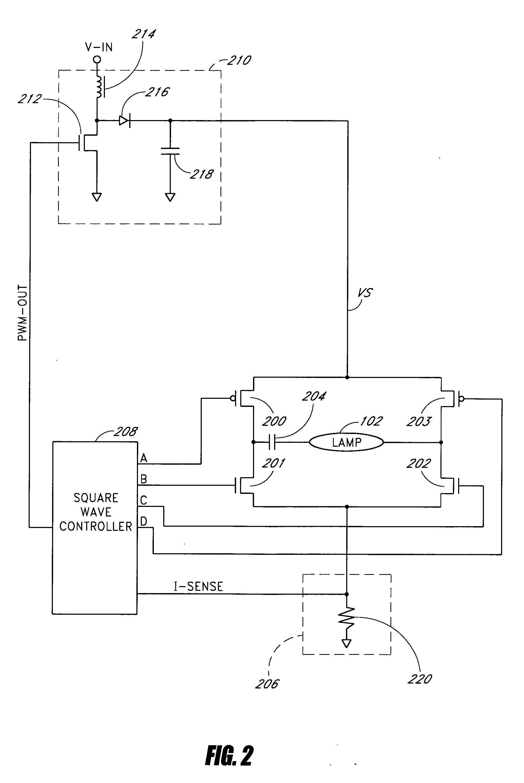
[0013] In one embodiment, the square wave voltage is directly coupled from the semiconductor switches to a fluorescent lamp connected in series with an AC coupling capacitor, which also operates as a DC blocking capacitor. The DC blocking capacitor ensures that DC current does not flow through the fluorescent lamp. The direct coupling of the semiconductor switches to the fluorescent lamp facilitates low operating frequencies (e.g., as low as 100 hertz). Low operating frequencies improve lamp current crest factor because the rise and fall times of the square wave voltage are relatively short in comparison to the pulse width (or period).
[0014] In another embodiment, the switching network includes an output transformer for coupling to the fluorescent lamp. For example, semiconductor switches are coupled to a primary winding of the output transformer, and the fluorescent lamp is coupled to a secondary winding of the output transformer. The output transformer has relatively low leakage inductance, relatively low secondary distributed capacitance, and relatively tight primary to secondary coupling. In one embodiment, the square wave voltage across the secondary winding of the output transformer has relatively fast transition times (e.g., less than one-twentieth of the period) and relatively small overshoots (e.g., less than 5%) to reduce lamp current crest factor for efficient operation.
[0015] In one embodiment, the power conversion circuit further includes a regulator (e.g., a boost regulator or a buck regulator). The regulator provides a desired supply voltage over a wide input voltage range. For example, a boost regulator provides a relatively high supply voltage to help strike and operate a fluorescent lamp, especially in topologies that directly couple semiconductor switches to the fluorescent lamp. In topologies with step-up transformers that couple the semiconductor switches to the fluorescent lamp, the supply voltage can be relatively lower. The fluorescent lamp can provide illumination in a display system for a flat panel computer monitor, a notebook computer, a hand held computer, or a liquid crystal display television.

Problems solved by technology

Fluorescent lamps are used in a number of applications where light is required but the power required to generate the light is limited.

Method used


Image

  • Square wave drive system
  • Square wave drive system
  • Square wave drive system

Examples


Embodiment Construction

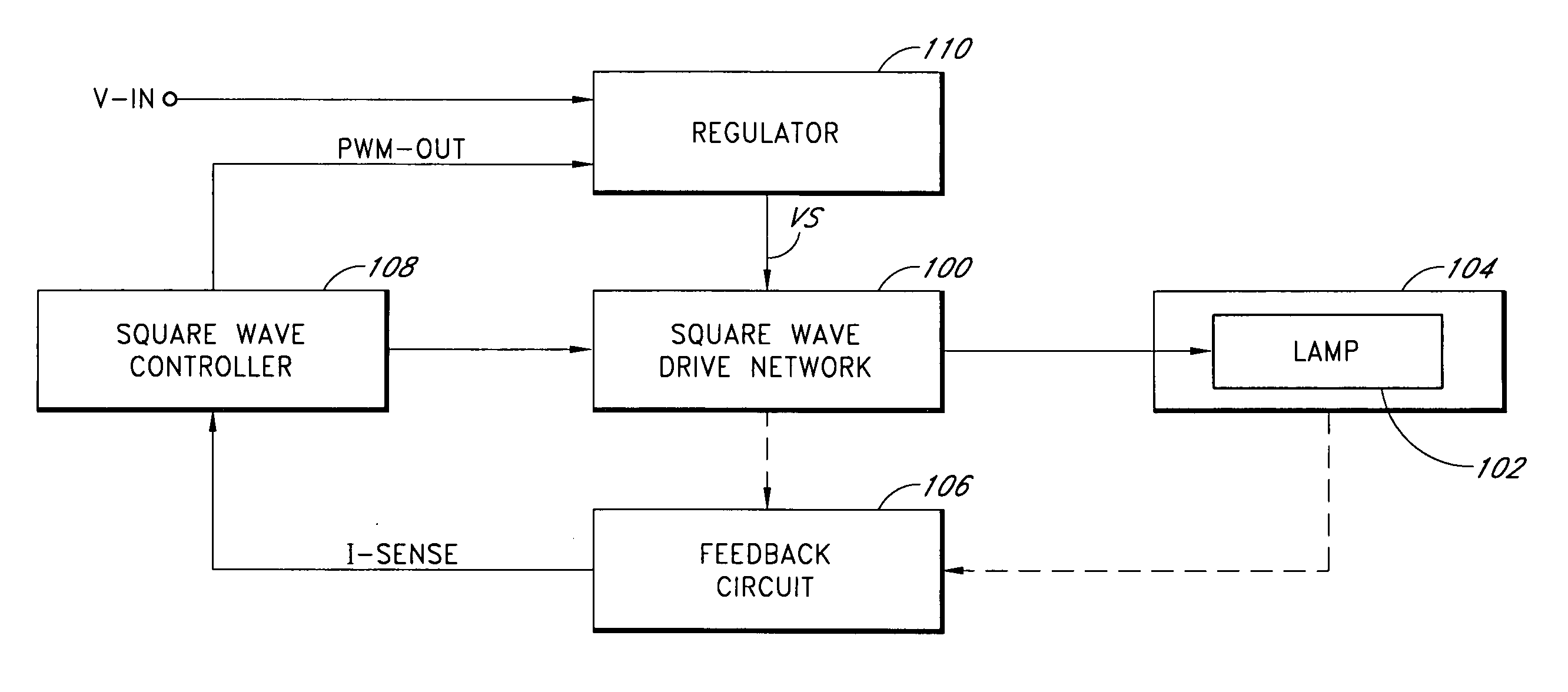
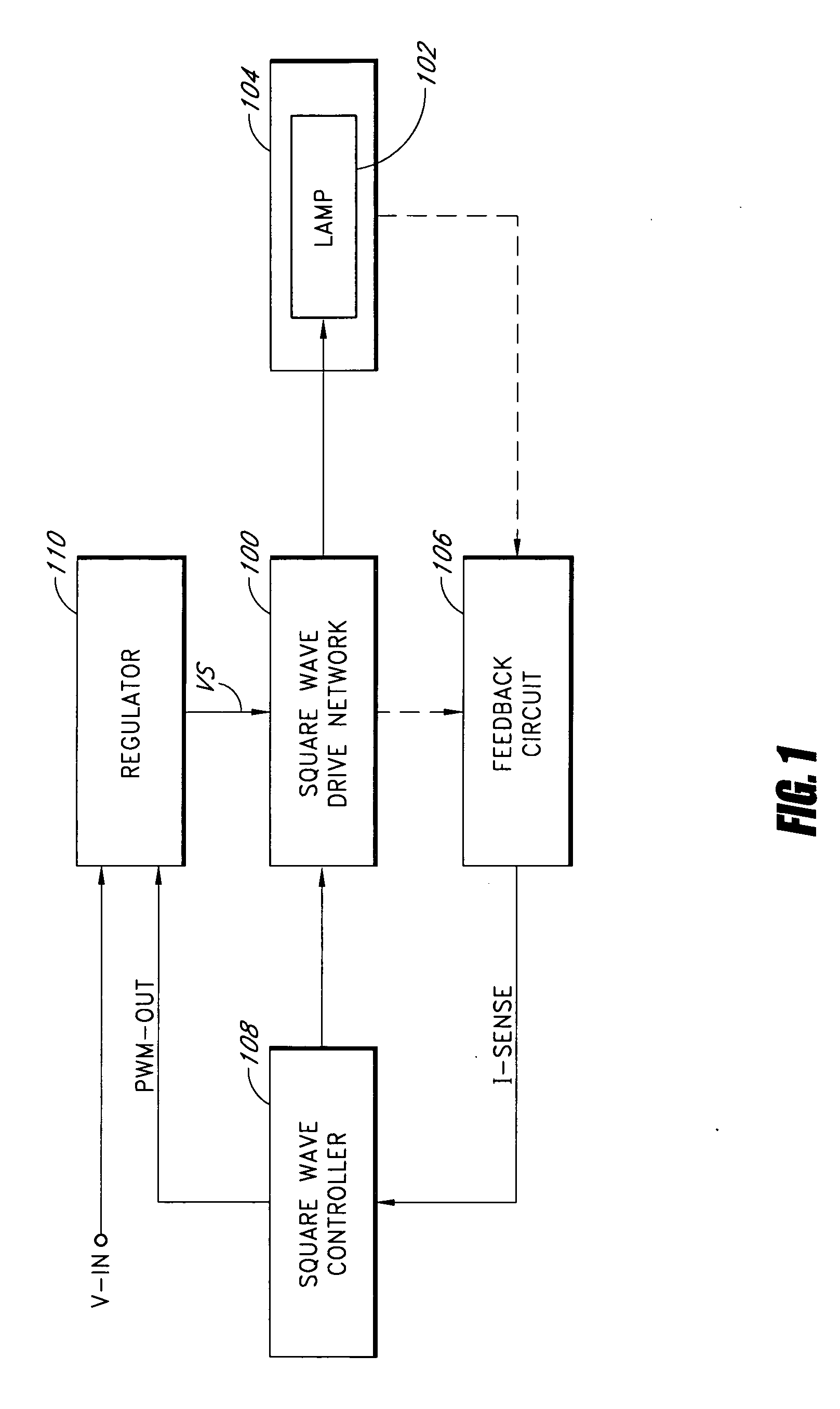
[0027] Embodiments of the present invention will be described hereinafter with reference to the drawings. FIG. 1 is a block diagram of a power conversion circuit (or a lamp inverter) according to one embodiment of the present invention. The power conversion circuit converts a substantially DC input voltage (V-IN) into a substantially square wave output voltage to drive a fluorescent lamp (e.g., a cold cathode fluorescent lamp (CCFL) or a hot cathode fluorescent lamp (HCFL)) 102. A lamp current flows through the fluorescent lamp 102 to provide illumination in an electronic device 104, such as, for example, a flat panel display, a notebook computer, a personal digital assistant, a hand held computer, a liquid crystal display television, a scanner, a facsimile machine, a copier, or the like.

[0028] The power conversion circuit includes a regulator 110, a square wave controller 108, a square wave drive network 100, and a feedback circuit 106. The regulator (or the input stage voltage re...


PUM


Abstract

A power conversion circuit improves lamp operating life and lamp efficiency by driving a fluorescent lamp with a square wave signal. The square wave signal is an alternating current signal with relatively fast transition times. The square wave signal advantageously reduces lamp current crest factor for more efficient operation of the fluorescent lamp.

Description

RELATED APPLICATIONS [0001] This application is a continuation of and claims priority benefit under 35 U.S.C. § 120 from U.S. patent application Ser. No. 10 / 463,280, filed Jun. 17, 2003, which claims the benefit of priority under 35 U.S.C. § 119(e) of U.S. Provisional Application No. 60 / 389,618 entitled “Lamp Inverter with Pre-Regulator,” filed on Jun. 18, 2002, and U.S. Provisional Application No. 60 / 392,333 entitled “Square Wave Drive System,” filed on Jun. 27, 2002, each of which is hereby incorporated herein by reference in its entirety. [0002] Applicant's U.S. patent application Ser. No. 10 / 463,289, filed Jun. 17, 2003, now U.S. Pat. No. 6,876,157, issued Apr. 5, 2005, is hereby incorporated by reference herein in its entirety.BACKGROUND OF THE INVENTION [0003] 1. Field of the Invention [0004] The present invention relates to a power conversion circuit for driving fluorescent lamps, such as, for example, cold cathode fluorescent lamps or hot cathode fluorescent lamps, and more ...

Claims


Application Information

Patent Timeline
Patent Type & Authority Applications(United States)
IPC IPC(8): H05B41/16H05B41/282H05B41/392
CPCH05B41/2828Y10S315/02Y10S315/07H05B41/3927
Inventor HENRY, GEORGE C.
Owner BANK OF AMERICA NAT TRUST & SAVINGS ASSOC
Learn More