Power supply controller

a power supply controller and controller technology, applied in the direction of power supply for data processing, process and machine control, instruments, etc., can solve the problems of affecting the reliability of photo printers, etc., to reduce the repair cost of failures.

Active Publication Date: 2006-02-02
FUJIFILM CORP
View PDF6 Cites 3 Cited by
  • Summary
  • Abstract
  • Description
  • Claims
  • Application Information

AI Technical Summary

Benefits of technology

[0009] An object of the present invention is to solve the problems based on the above-described conventional techniques and to provide a power supply controller capable of preventing a component in a device from becoming out of control to cause runaway when a failure occurs in a power supply. Another object of the present invention is to provide a power supply controller capable of identifying the rough cause of the occurrence of a failure when the failure occurs in a power supply so as to reduce repair cost for the failure.

Problems solved by technology

However, since a photo printer such as a Minilab system has a large power capacity, the use of the UPS for the photo printer significantly increases cost.
Therefore, the complete backup by the UPS has a limit.
Moreover, in some problems occurring in the power supply system, various situations sometimes occur in an unrepeated fashion.
For example, if a failure such as an instantaneous blackout occurs in a power supply system of the above mentioned photo printer while photographic paper is being exposed to light with a laser light source, there is no guarantee that a printed image being developed on the photographic paper at that time is correctly output.
As a result, if a photo print is passed to a customer while the occurrence of the failure in the power supply system remains unnoticed, such a problem is discovered only after the customer makes a compliant.
The latter case induces a more serious problem in view of safety.
In this case, a mechanical component in the device sometimes becomes out of control to cause runaway, thereby damaging the system.
Furthermore, the cause of a failure in a power supply system is difficult to identify.
Therefore, in many cases, it takes a considerable time to determine the cause.
Moreover, since the corresponding components are all replaced without identifying the cause of the failure, there arises another problem in that repair cost is disadvantageously increased.
However, if a failure occurs in the power supply system, the device itself is not activated.
Therefore, the cause of a failure in the power supply system cannot be identified in the self-diagnosis using a software.

Method used


Image

  • Power supply controller
  • Power supply controller
  • Power supply controller

Examples


Embodiment Construction

[0045] Hereinafter, a power supply controller according to the present invention will be described in detail based on a preferred embodiment illustrated in the accompanying drawings.

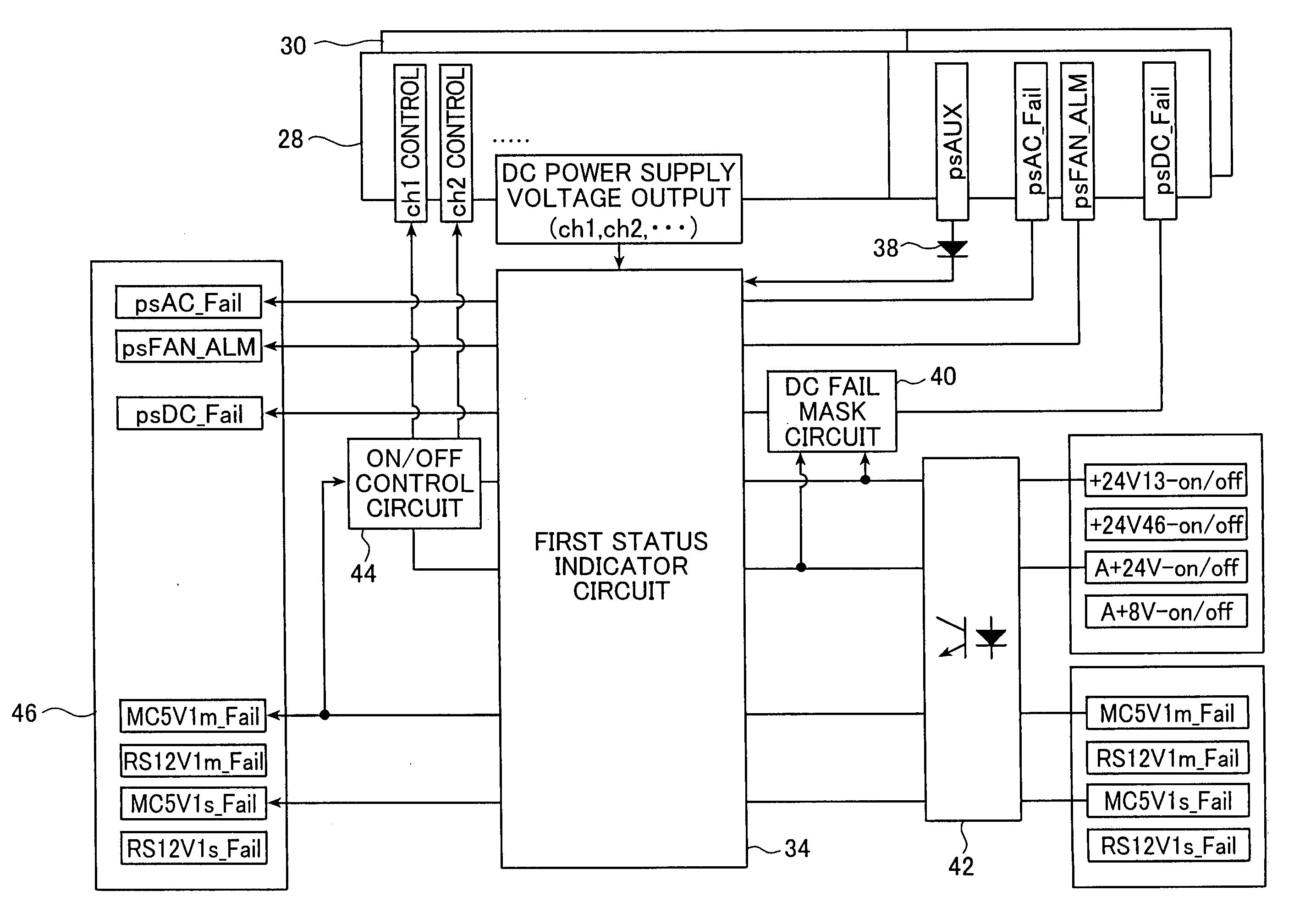
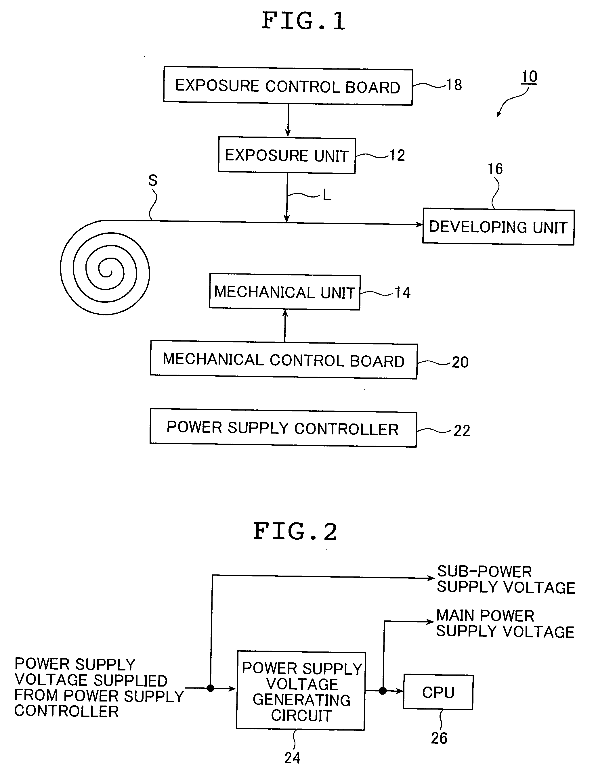
[0046]FIG. 1 is a schematic block diagram showing an internal structure of an image recording device, for which a power supply controller according to an embodiment of the present invention is used. An image recording device 10 shown in FIG. 1 is a digital photo printer for recording an image in accordance with image data on a recording medium (photographic paper) S. The image recording device 10 includes as components: an exposure unit 12; a mechanical component unit (hereinafter, referred to simply as a mechanical unit) 14; and a developing unit 16. The image recording device 10 also includes as control boards: an exposure control board 18; and a mechanical component control board (hereinafter, referred to as a mechanical control board) 20, and further includes a power supply controller 22 according t...


PUM


Abstract

A power supply controller is used in a device including at least one component and at least one control board for controlling an operation of each component, and includes: a power supply section; and a power supply board for independently supplying a power supply voltage output from the power supply section to each of the component and the control board. The power supply board includes an output control circuit for independently controlling to output or to stop outputting the power supply voltage supplied from the power supply board to each of the components based on a signal indicating one of a normal state and an abnormal state of the power supply voltage used in each control board, which is fed back to the power supply board from each control board when the power supply voltage is supplied from the power supply board to each control board.

Description

[0001] The entire contents of literatures cited in this specification are incorporated herein by reference. BACKGROUND OF THE INVENTION [0002] The present invention relates to a power supply controller used in various devices including, for example, a photo printer for printing a picture on a recording medium (photographic paper). [0003] As a safety measure for an occurrence of a failure in a power supply system of a device, a UPS (uninterruptible power supply) is mainly used. Specifically, when a failure occurs in a device including the UPS, a power supply is switched to the UPS so as to automatically shut the device down to prevent a malfunction and the like. However, since a photo printer such as a Minilab system has a large power capacity, the use of the UPS for the photo printer significantly increases cost. Therefore, the complete backup by the UPS has a limit. [0004] Moreover, in some problems occurring in the power supply system, various situations sometimes occur in an unre...

Claims


Application Information

Patent Timeline
Patent Type & Authority Applications(United States)
IPC IPC(8): G06F7/02
CPCG06F1/30B41J29/393
Inventor YANAGI, KOUJIFUKAZAWA, JUN
Owner FUJIFILM CORP
Why Eureka
Try Eureka