Vehicle telemetric system

a telemetric system and vehicle technology, applied in the field of motor vehicles, can solve the problems of not having a continuous geographic coverage, high cost and waste of resources, and not having a network for frequent and regular access to potentially very large numbers of vehicles

Active Publication Date: 2006-02-02
GEOTAB
View PDF12 Cites 98 Cited by
  • Summary
  • Abstract
  • Description
  • Claims
  • Application Information

AI Technical Summary

Benefits of technology

[0016] It is an objective of the present invention to provide a vehicle telemetric system, which would avoid or reduce the above mentioned drawbacks.

Problems solved by technology

A problem of access may arise, due to the reliance on a single wireless network between the vehicle and the central host.
The use of a single, virtually ubiquitous, wireless network is possible in principle (viz. the cellular telephone network, or a satellite based network), but the use of such a network for frequent and regular access to a potentially very large number of vehicles is both expensive and wasteful of resources.
There is not a continuous geographic coverage of WLANs, and a vehicle may frequently be outside the reach of any WAP.
Furthermore, not every WLAN is designed or intended to operate with all vehicles.
However in a general surveillance or remote monitoring application, where the vehicle is free to roam, the driver may not even be aware of the data collection taking place, or of the boundaries of a WLAN the modem in the vehicle is currently accessing.
While providing an elegant way of “hiding” the problem, thus possibly simplifying software design at the host, this solution does not address the practical aspects of providing continuity of information using a generally available protocol (IP version 4) nor does it take into account the uncertain, often intermittent, presence of vehicles within reach of a WLAN.
There exists thus a problem to ensure continuity of the effective data communication between the vehicle and the central host.
The method described in the above cited U.S. Pat. No. 5,564,070 for providing continuity of communication is thus not directly applicable to the problem of providing continuity of information in a motor vehicle telemetric system.

Method used


Image

  • Vehicle telemetric system
  • Vehicle telemetric system
  • Vehicle telemetric system

Examples


Embodiment Construction

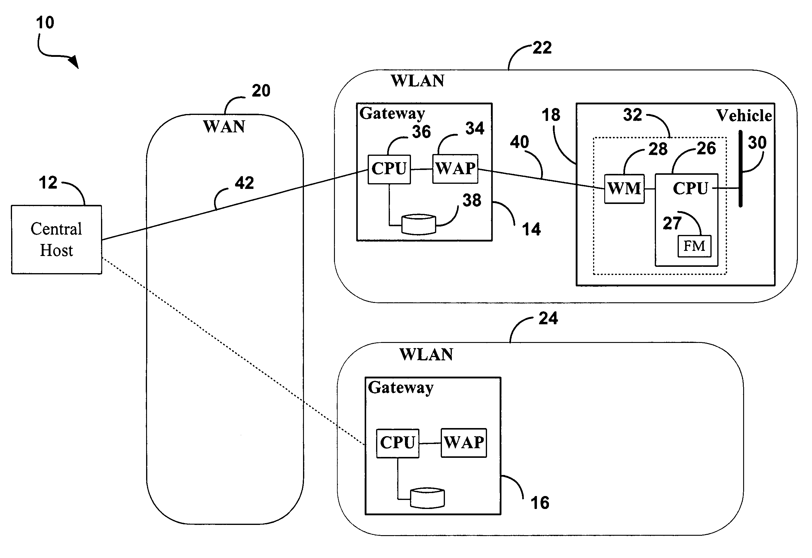
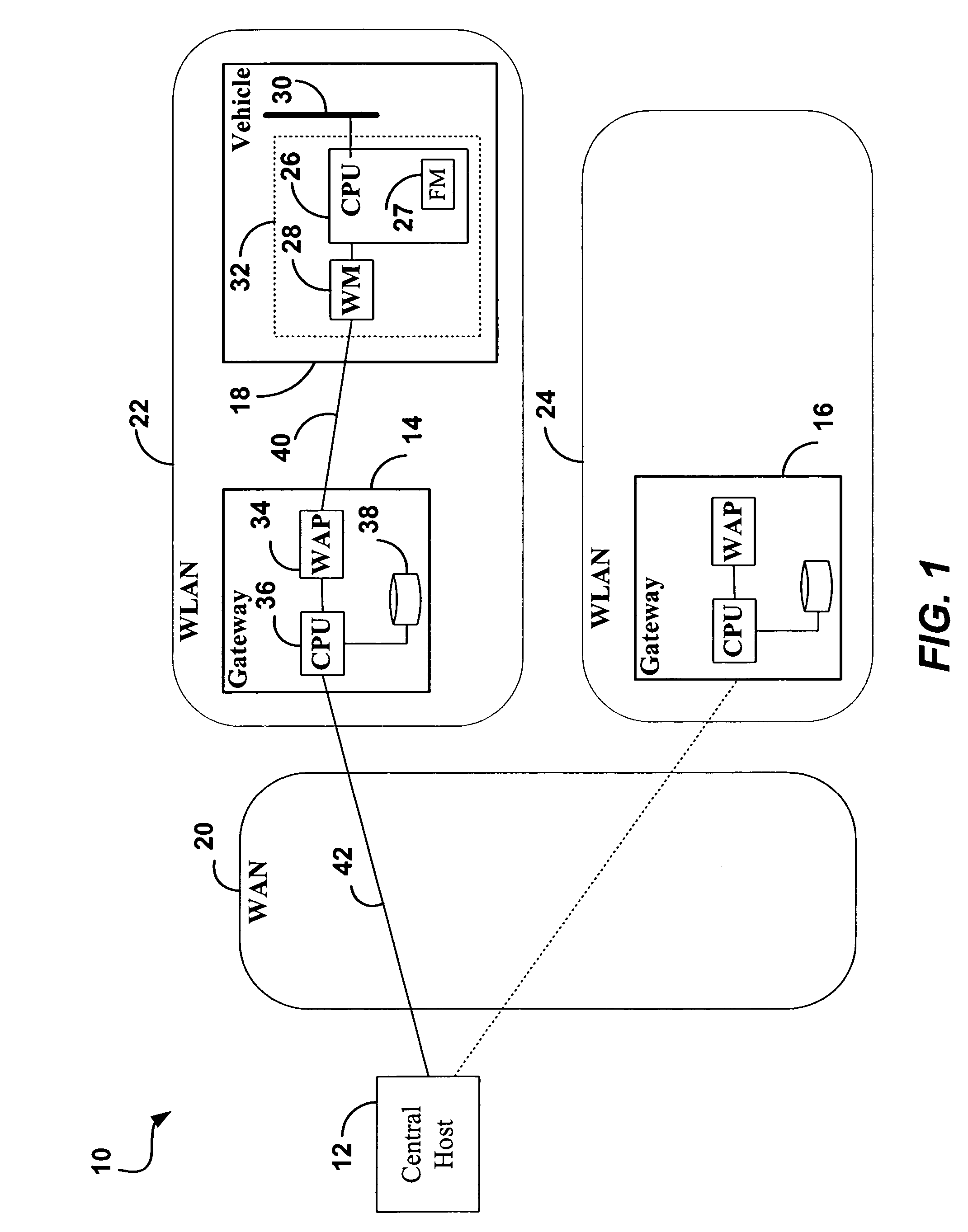
[0071]FIG. 1 shows the architecture of a vehicle telemetric system 10, including a central host 12; a first gateway 14; a second gateway 16; and a vehicle 18. The second gateway 16 is similar to the first gateway 14. The gateways 14 and 16 are connected with the central host 12 over a wide area network (WAN) 20. The coverage area of a first Wireless Local Area Network (WLAN) 22 exists around the first gateway 14. Similarly, the coverage area of a second WLAN 24 exists around the second gateway 16.

[0072] The vehicle 18 is shown inside the coverage area of the first WLAN 22, and thus within reach of the first gateway 14.

[0073] The vehicle telemetric system 10 may include additional gateways (not shown) having additional coverage areas of additional WLANs (not shown), and includes additional vehicles (not shown).

[0074] At some other time (not shown) the vehicle 18 is inside the coverage area of the second WLAN 24, and thus within reach of the second gateway 16.

[0075] At yet another...


PUM


Abstract

A vehicle telemetric system comprises vehicle interface units (VIUs), wireless gateways, and a central host. The VIU in a vehicle collects data over the OBD-II bus and stores the data in the form of Data Point Records (DPRs) in an on-board flash memory. When the VIU is within wireless range of a gateway, it establishes a WiFi (802.11b) connection with the gateway, and submits stored DPRs to the gateway, to be stored in permanent storage at the gateway. The gateways communicate with the central host over a wide area network (WAN). When a gateway has gathered new DPRs from a VIU, it submits these to the central host. Databases in the gateways as well as in the central host are maintained and synchronized to track received DPRs by sequence number and originating VIU. In conjunction with specific protocols, all DPRs are thus collected reliably, even though communication with a vehicle may be intermittent. Efficient use of WiFi bandwidth is made by avoiding the unnecessary collection of duplicate DPRs.

Description

FIELD OF THE INVENTION [0001] The invention relates to motor vehicle telemetric systems, in which an on-board computer transmits vehicle related data to a central host computer over a wireless network. BACKGROUND OF THE INVENTION [0002] Most motor vehicles have in recent years been equipped with on-board computers connected to sensors located in various systems in the motor vehicle, for example the engine, the exhaust system, and the like. [0003] The Society of Automotive Engineers (SAE) has set standards which include a standard connector plug and a set of diagnostic test signals that technicians use when adjusting or repairing the motor vehicle. The standard connector plug and set of test signals, today, is known collectively as OBD-II (On-Board-Diagnostic, version 2) which applies to all cars and light trucks built after Jan. 1, 1996. [0004] The on-board computers may also be coupled through the OBD-II interface to an on-board equipment containing a wireless modem, and thence to ...

Claims


Application Information

Patent Timeline
Patent Type & Authority Applications(United States)
IPC IPC(8): G08C19/22
CPCG07C5/008
Inventor ZOLADEK, JACEK GRZEGORZGOODALL, COLIN DAVIDPREECE, DOUGLAS JOHNPEPPER, GARY THOMAS
Owner GEOTAB
Why Eureka
Try Eureka