Optical fiber connected body with mutually coaxial and inclined cores, optical connector for forming the same, and mode conditioner and optical transmitter using the same

a technology of optical fiber and coaxial core, applied in the direction of optics, instruments, optical light guides, etc., can solve the problems of insufficient suppression of abnormal mode dispersion and inability to receive accurate signals in receivers, and achieve the effect of efficient transmission of signals

Inactive Publication Date: 2006-02-02
KYOCERA CORP
View PDF5 Cites 30 Cited by
  • Summary
  • Abstract
  • Description
  • Claims
  • Application Information

AI Technical Summary

Benefits of technology

[0019] Preferably, the first optical fiber is a single mode optical fiber and the second optical fiber is a multimode optical fiber. Since the core center of the first optical fiber and the core center of the second optical fiber are eccentric, a

Problems solved by technology

In the conventional configuration, however, when the transmission speed becomes faster and the transmission distance becomes longer, abnormal dispersion

Method used


Image

  • Optical fiber connected body with mutually coaxial and inclined cores, optical connector for forming the same, and mode conditioner and optical transmitter using the same
  • Optical fiber connected body with mutually coaxial and inclined cores, optical connector for forming the same, and mode conditioner and optical transmitter using the same
  • Optical fiber connected body with mutually coaxial and inclined cores, optical connector for forming the same, and mode conditioner and optical transmitter using the same

Examples


embodiment 1

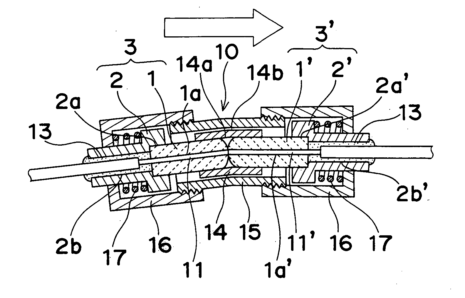
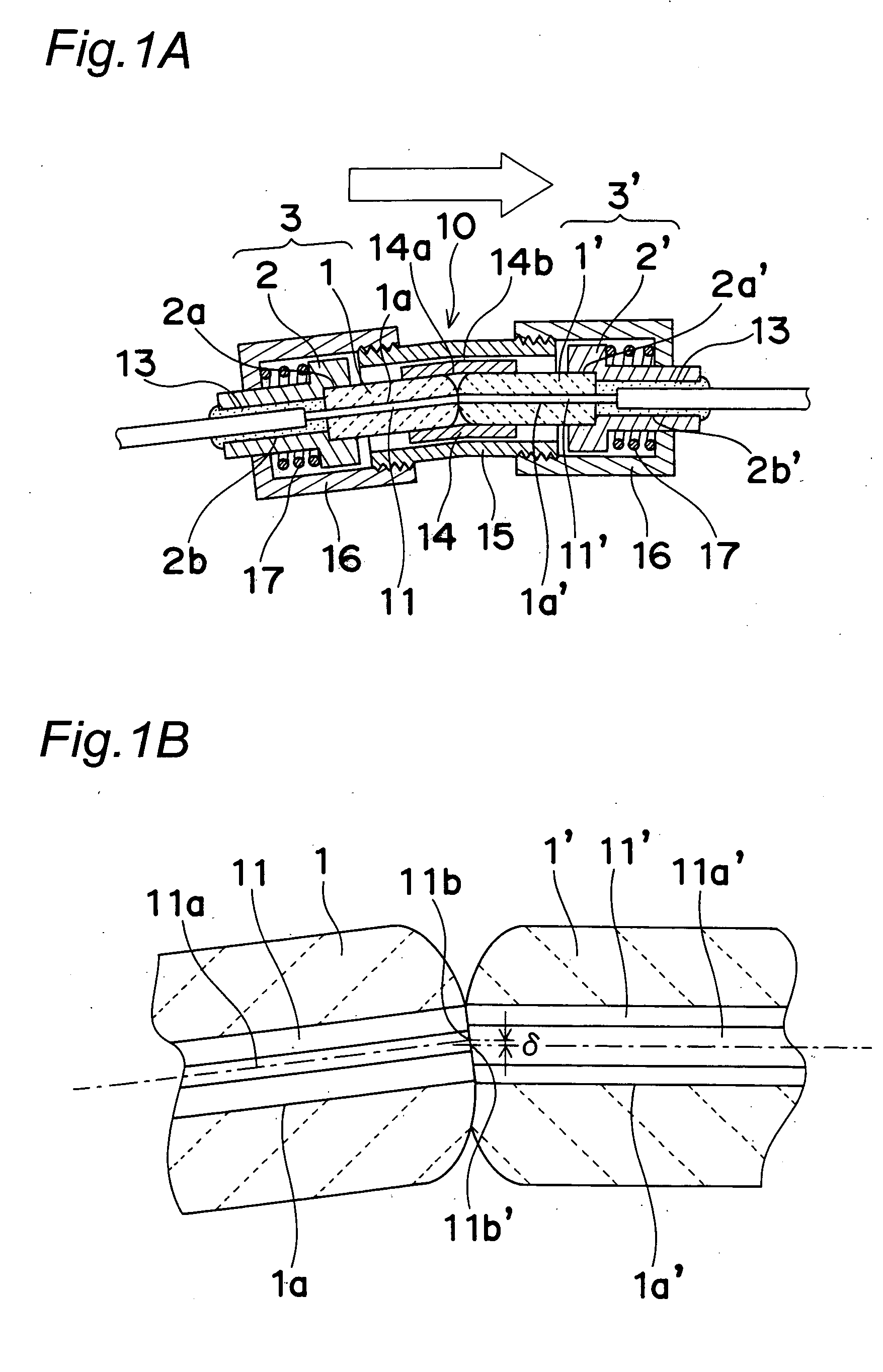
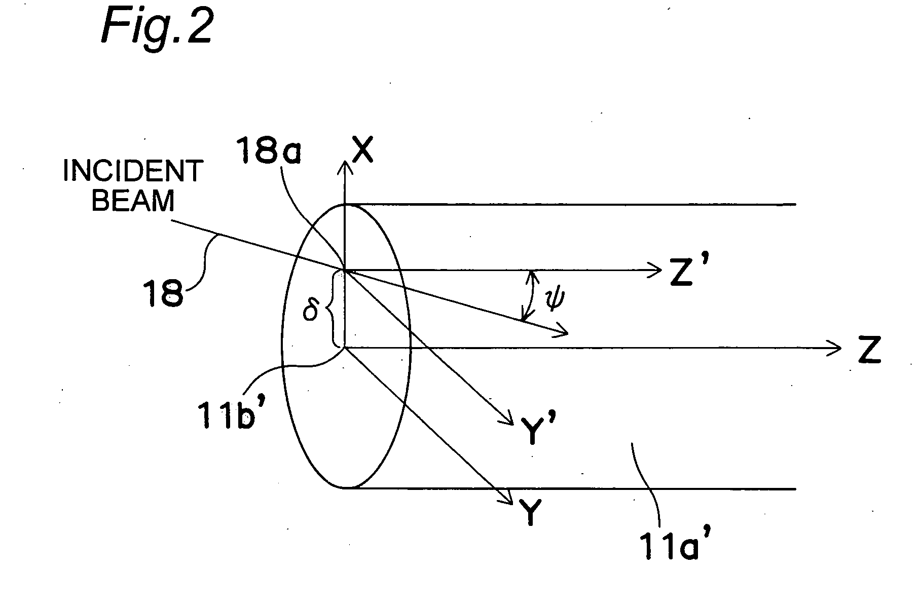
[0062] In this embodiment, the invention is applied in an optical connector. The optical connector of the embodiment is an optical connector for connecting both ends of a pair of optical fibers, in which the optical fibers are connected so that the core centers of the optical fibers are mutually deviated, and that an incident beam from one optical fiber enters at an inclination to the axial center of other optical fiber.

[0063] According to the optical connector of the embodiment, when a single mode optical fiber is connected to a multimode optical fiber, abnormal dispersion occurring in the multimode optical fiber can be suppressed. Therefore, even at fast transmission speed and long transmission distance, abnormal dispersion of modes is suppressed, and signals can be transferred at high efficiency. Dispersion occurring in the multimode optical fiber is specifically described below.

[0064] The multimode optical fiber of graded index type (called multimode optical fiber hereinafter)...

embodiment 2

[0083] In this embodiment, the invention is applied in a mode conditioner. The mode conditioner of the embodiment has a junction of fusing and bonding one end of the single mode optical fiber and one end of the multimode optical fiber, and a patching cord having an optical connector is provided at other end of the both. The central positions of cores at the junction are set eccentric mutually, and the central axes of the cores are inclined, and fused and adhered.

[0084]FIG. 4A is a block diagram of mode conditioner 40 of the embodiment. The mode conditioner 40 of the embodiment is a mode conditioner 40 of patching cord type for bonding to an integral type optical transceiver 32. The patching cord is a fiber code that has optical connecters on both ends. In the embodiment shown in FIG. 4A, a short distance from a transmitting device 31 such as LAN device to an optical fiber end panel (patch panel) 34 is connected by a patching code. A dual mode conditioner 40 shown in FIG. 4A has a s...

embodiment 3

[0093] In this embodiment, the invention is applied in an optical transmitter with a mode conditioner. The optical transmitter of the embodiment has a split sleeve disposed on the optical axis of laser diode, and a fiber stab having a single mode optical fiber is inserted at the light incident side of the split sleeve, while a plug ferrule having an optical fiber is inserted at the light exit side. The fiber stab and plug ferrule can abut against each other at opposite ends. The single mode optical fiber in the fiber stab and arbitrary optical fiber in the plug ferrule are connected to each other, with the central positions of the cores being deviated relatively, and the mutual optical axes being inclined.

[0094]FIG. 5A is a sectional view of the optical transmitter of the invention. The optical transmitter in FIG. 5A has a laser diode 51, and it is designed to realize optical transmission by connecting to a plug ferrule 55 having a multimode optical fiber 56. The optical transmitte...


PUM


Abstract

An optical fiber connected body including a first optical fiber having a core and a clad, and a second optical fiber having a core and a clad, with its end connected optically to an end of the first optical fiber, in which the core center of the first optical fiber and the core center of the second optical fiber are mutually deviated at the interface of the first optical fiber and the second optical fiber, a light beam entering the second optical fiber from the first optical fiber is inclined to the central axis of the second optical fiber.

Description

BACKGROUND OF THE INVENTION [0001] 1. Field of the Invention [0002] The present invention relates to an optical fiber connected body in which optical fibers are connected with each other, which is used in optical communications, an optical connector for forming the same, and a mode conditioner and an optical transmitter optical connector using the same. [0003] 2. Description of the Related Art [0004] Systems used for connecting computers include 10-megabit Ethernet (registered trademark) and 100-megabit Fast Ethernet (registered trademark), and they are further to be replaced by gigabit Ethernet (registered trademark) of larger transmission capacity. For superfast large capacity transmission, development has been started for 10-gigabit Ethernet (registered trademark). [0005] For high speed and large capacity of data transmission, transmission system must be changed from electrical signal to optical signal. Optical signal is further demanded to be changed from optical signal emitted ...

Claims


Application Information

Patent Timeline
IPC IPC(8): G02B6/36
CPCG02B6/3829G02B6/381
Inventor KOBAYASHI, YOSHIHIRO
Owner KYOCERA CORP
Why Eureka
Try Eureka