Gear grinding machine

a grinding machine and gear technology, applied in the direction of instruments, programme control, abrasive surface conditioning devices, etc., can solve the problems of tooth profile modification, shortened service life, and worn threaded grinding wheels

Active Publication Date: 2006-02-02
MITSUBISHI HEAVY IND MACHINE TOOL CO LTD
View PDF9 Cites 31 Cited by
  • Summary
  • Abstract
  • Description
  • Claims
  • Application Information

AI Technical Summary

Benefits of technology

[0056] an NC control function unit for adjusting the synchronization between the moving motion in the Z-axis direction of the threaded grinding wheel and the rotary motion of the table so that a helix angle formed in the work is changed by the helix angle modification amount, and for modifying a moving distance in the Y-direction of the threaded grinding wheel per rotation of the threaded grinding wheel by the lead correction amount to adjust the moving distance in the Y-direction of the threaded grinding wheel per rotation of the threaded grinding wheel.

Problems solved by technology

As grinding proceeds, the threaded grinding wheel wears, and its sharpness decreases.
Such correction of the helix form deviation inevitably results in the modification of the tooth profile.

Method used


Image

  • Gear grinding machine
  • Gear grinding machine
  • Gear grinding machine

Examples


embodiment

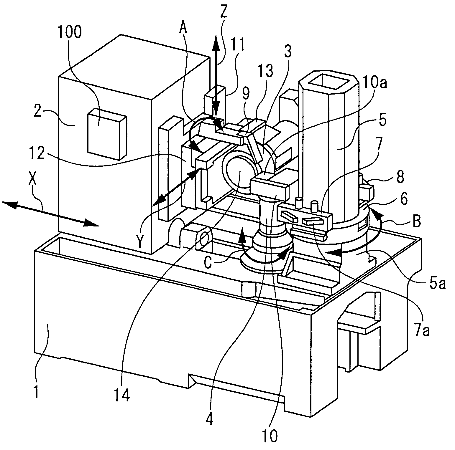
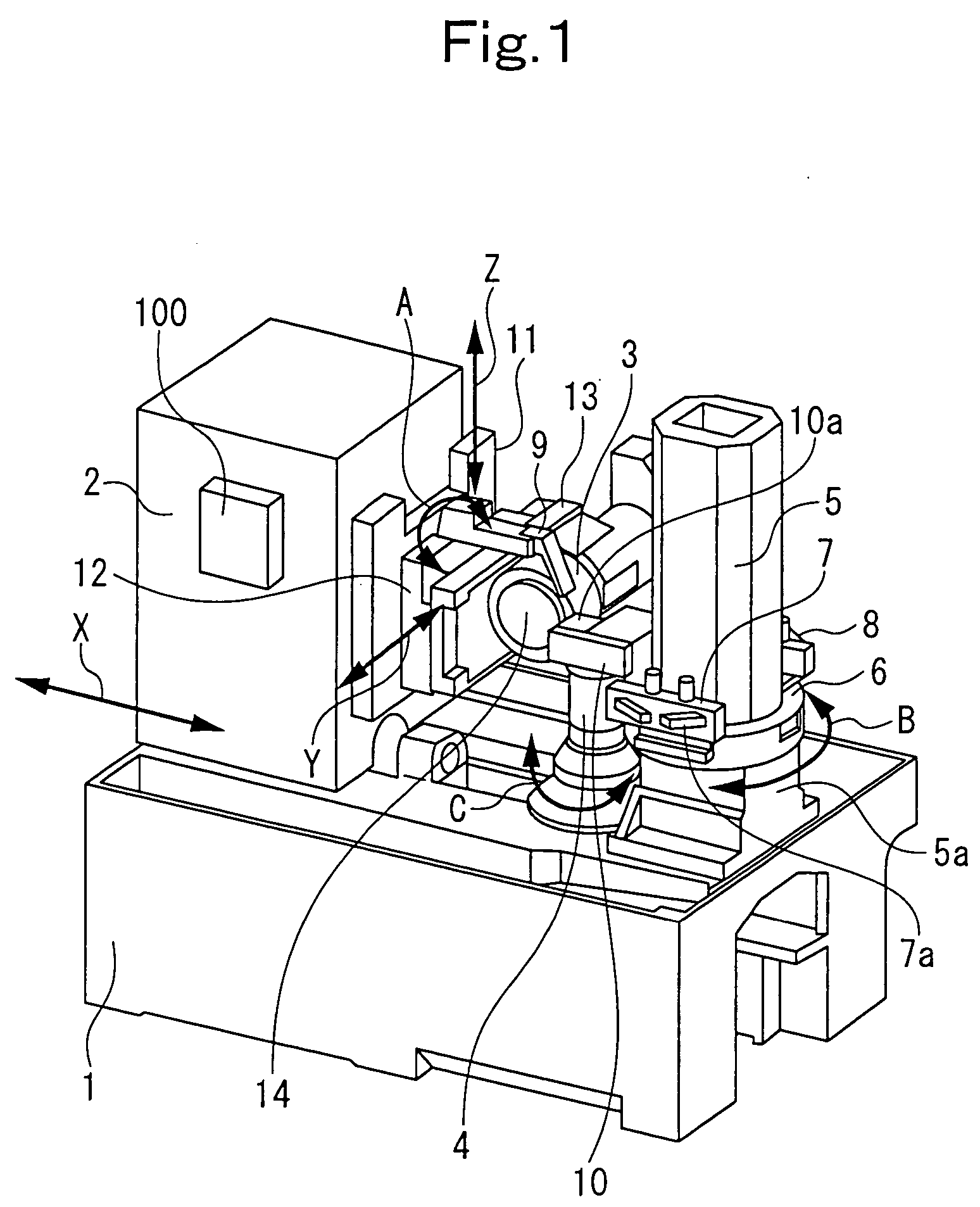
[0123] In the Embodiment of the present invention, if the measurement of the dimensions of a gear, which has been produced by grinding by means of the gear grinding machine shown in FIG. 1, shows a gear shape error, the actions of the gear grinding machine are modified by modification and computing function units of the NC device 100 in the manner described below.

[0124]FIG. 7 shows modification and computing function units extracted from the computing function units of the NC device 100. Needless to say, the NC device 100 exercises ordinary numerical control, namely, numerical control of the movements in the X, Y, Z, A and C directions of the moving mechanism, the rotational driving of the threaded grinding wheel 3 by the grinding spindle 14, and the rotational driving of the table 4. However, such ordinary NC function units are not shown.

[0125] According to the present embodiment, the dimensions of a gear produced by grinding are measured by a measuring device or the like. If the...


PUM

PropertyMeasurementUnit
pressure angle error computingaaaaaaaaaa
pressure angle erroraaaaaaaaaa
helix angleaaaaaaaaaa

Abstract

To correct the tooth profile error of a ground gear, the wheel angle of a threaded grinding wheel is modified by dressing the threaded grinding wheel by a dressing device. To correct the helix form deviation of a ground gear, namely, to modify the helix angle of the gear, synchronization between the moving motion in the Z-direction of the threaded grinding wheel and the rotary motion of a table for installation of the gear is adjusted. When the helix form deviation is corrected by adjustment of the synchronization, a tooth profile change inevitably occurs. In consideration of the tooth profile change, correction of the tooth profile error by dressing is made.

Description

BACKGROUND OF THE INVENTION [0001] 1. Field of the Invention [0002] This invention relates to a gear grinding machine arranged to perform grinding (gear machining) using a threaded grinding wheel, and equipped with a dressing device for dressing the threaded grinding wheel. The gear grinding machine can easily correct an error (dimensional error), if any, in a ground gear. [0003] 2. Description of the Related Art [0004] A gear grinding machine, in which a gear-shaped workpiece after heat treatment is ground by “a threaded grinding wheel”, a gear grinding tool, to finish a gear, has so far been known. The threaded grinding wheel is an annular grinding wheel having threads (rack teeth) formed spirally on its outer peripheral surface. Grinding is performed by numerically controlling the positions in an orthogonal coordinate system (positions on the X-axis, Y-axis and Z-axis) of the threaded grinding wheel, the rotational speed of the threaded grinding wheel, and the rotational speed of...

Claims


Application Information

Patent Timeline
Patent Type & Authority Applications(United States)
IPC IPC(8): B24B49/00B23F5/04B24B53/085
CPCB23F23/1225B24B19/009G05B2219/49247G05B19/186G05B2219/45214B24B53/085B23F1/02B23F5/02
Inventor YANASE, YOSHIKOTOKATSUMA, TOSHIFUMI
Owner MITSUBISHI HEAVY IND MACHINE TOOL CO LTD
Why Eureka
Try Eureka