Extending wireless communication RF coverage inside building

a wireless communication and building technology, applied in the field of wireless communication systems, can solve the problems of reducing the accuracy of loss estimation, and reducing the repeater gain

Active Publication Date: 2006-02-02
LUCENT TECH INC +1
View PDF11 Cites 84 Cited by
  • Summary
  • Abstract
  • Description
  • Claims
  • Application Information

AI Technical Summary

Benefits of technology

[0016] In one example, the power level of the received pilot signal associated with a CDMA / UMTS “access and control channel” is used to adjust the gain of the repeater antenna assembly that allows for finding the highest possible repeater gain while avoiding base station receiver desensitization. In another example, the aggregate received signal power level is used to estimate the loss in CDMA / UMTS systems eliminating the need for pilot demodulating circuitry at diminished loss estimation accuracy. Gain offsets are described to take into account the diminished accuracy. In yet again another example, the technique is applied to GSM and its BCCH access and control channel.
[0017] Even with the highest possible repeater gains, there may not be enough signal boost to provide the desired minimum inside RF coverage. One disclosed example repeater antenna assembly includes RF signal level indicators that identify when outside RF signal conditions can support a minimum desired inside link budget. Thus, operators can choose how reliable inside RF coverage should be by setting the RF signal level indicator thresholds. Other RF signal level indicators facilitate finding an optimal spot for the antenna assembly to avoid deep Rayleigh fades.

Problems solved by technology

One limitation on such communications has been that the ability to obtain an adequate signal within a home, for example, can be too limited to provide confidence for an individual to rely solely upon a mobile unit for all telecommunications from their home.
There are a variety of factors contributing to the poor radio frequency (RF) coverage in and around many homes.
For example, the metallic content of many home or building structures can provide an RF block or otherwise interfere with adequate signal transmission.
Additionally, the various metal objects and the structure of the internal walls, for example, in many cases prevent adequate interior RF coverage so that an individual cannot rely upon their mobile unit on a consistent basis in all locations within the home.
The first approach, which can be referred to as “RF building blasting from the outside in”, requires a repeater antenna site such as a rooftop or tower that is frequently prohibitively expensive or not attainable in many residential areas.
Unfortunately, RF building blockage is uneven and the resulting inside RF coverage is unpredictable and often inadequate.
There may not be sufficient inside signal levels where needed depending upon where inside the house a call is being made, the house location relative to the serving base station location, building construction, repeater site location, and orientation of the repeater antennas.
The need for a technician and the installation of cabling and the external antenna raises costs outside the reach of many homeowners and small enterprise owners.
A significant challenge to a designer of a system to maximize RF coverage into buildings such as homes, for example, is that increasing the amplifier gains generally increases inside RF coverage until either base station receiver desensitization or repeater positive feedback occurs.
When either one of these conditions arises, the base station or the repeater can no longer function properly resulting in loss of inside coverage, outside macrocell coverage and traffic capacity or both.
Base station receiver desensitization arises when the repeater injects noise into the radio receiver raising its noise floor.
Since the noise level increases within the radio receiver, higher receive signals are required to offset the increase in noise thus causing the “desensitization.” This is especially problematic for CDMA systems.
Whenever the repeater gain is set too high, the net path gain from amplifier output to input exceeds unity and the repeater amplifier then oscillates out of control rendering the repeater or base station inoperative.
They currently do not have the ability to automatically set their amplifier gains to the highest possible setting while avoiding base station receiver desensitization and positive feedback.
They do not generally exploit characteristics of a particular CAI to automatically set amplifier gains necessary to achieve the best possible inside performance.
While some have positive feedback cancellation circuits, they can still oscillate out of control when there is insufficient isolation between repeater antennas.
This can occur when the design of the antenna assembly is not integrated with the repeater amplifier circuit design.
Others have circuits that automatically step the repeater gains back until positive feedback ceases but do not protect against base station receiver desensitization.
Nor do they provide RF signal level thresholds that allow the repeater to only operate when a desired minimum inside link budget can be supported.

Method used


Image

  • Extending wireless communication RF coverage inside building
  • Extending wireless communication RF coverage inside building
  • Extending wireless communication RF coverage inside building

Examples


Embodiment Construction

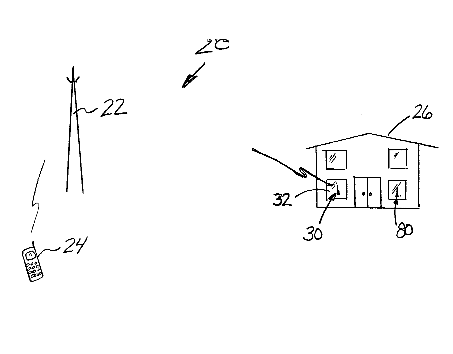
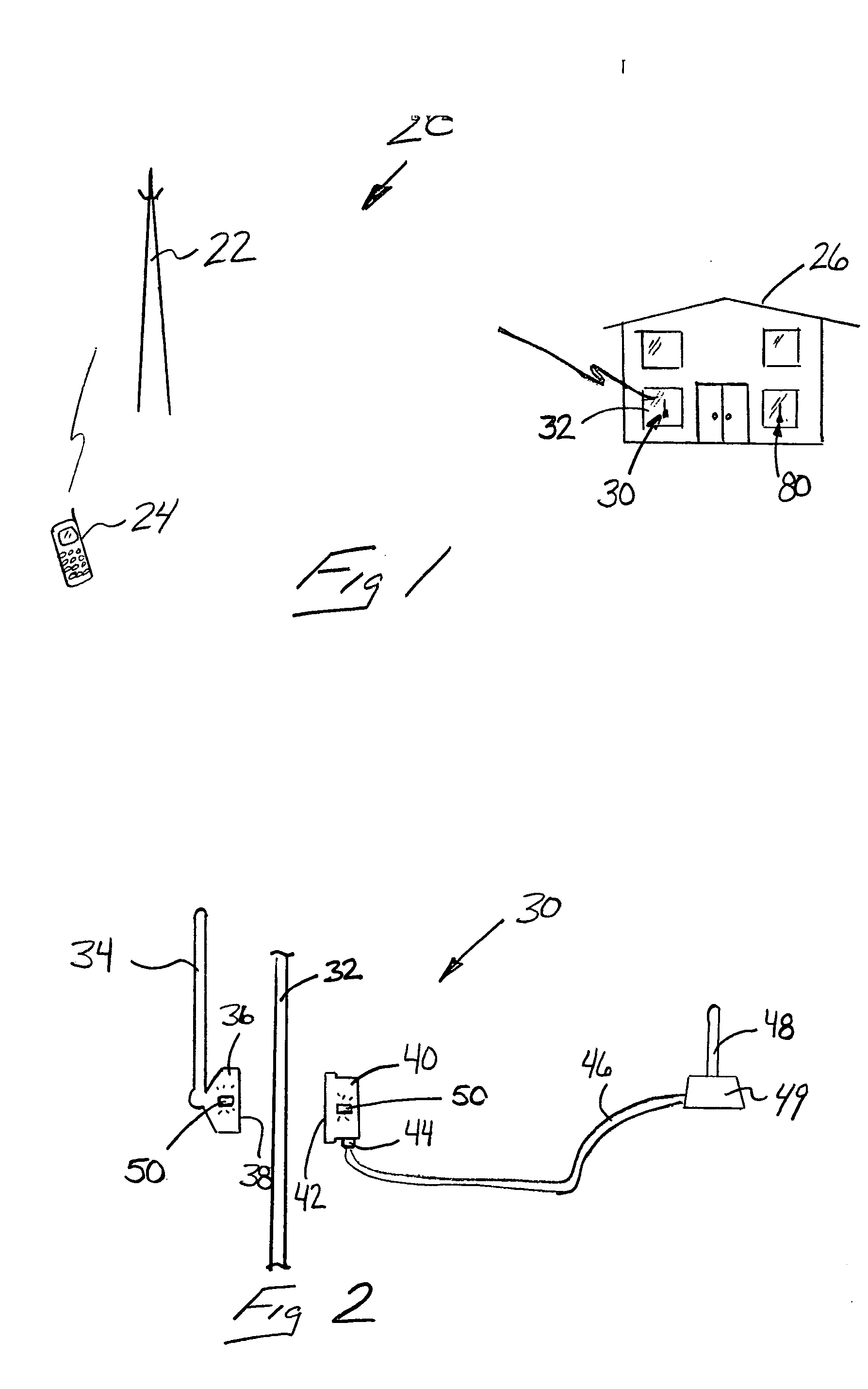
[0024]FIG. 1 schematically illustrates a wireless communication system 20 showing selected portions of the system. A base station 22 facilitates wireless communication with a plurality of mobile units 24. Such communications occur in a known manner.

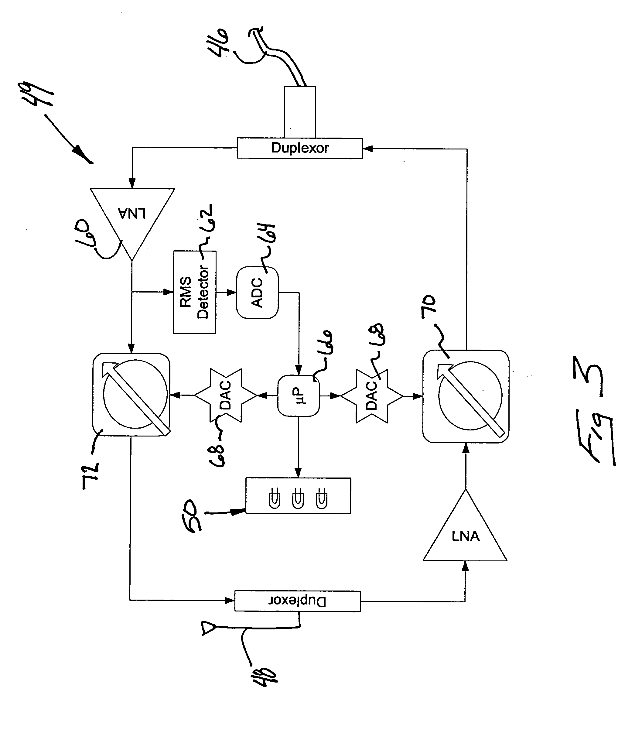
[0025] The example of FIG. 1 is also well suited for providing wireless radio frequency (RF) signal coverage within a building 26, which may be a home, a small enterprise, or part of an office building, for example. In the illustrated example, a repeater antenna assembly 30 is associated with at least one window 32 of the building 26. The repeater antenna assembly 30 provides at least a minimum desired inside link budget to provide RF coverage within the building 26 based upon signals received from the base station 22. The example repeater antenna assembly 30 is designed to operate at the highest possible gains that avoid positive feedback and base station receiver desensitization.

[0026] Base station receiver desensitization does not oc...


PUM


Abstract

A wireless communication system includes at least one repeater antenna assembly for providing adequate RF coverage within a building, such as a home. An example repeater antenna assembly has an automatically adjustable gain that is controlled responsive to a pathloss associated with a received signal to avoid base station transceiver desensitization and positive feedback. A disclosed assembly avoids base station desensitization and positive feedback. Another disclosed technique maintains a selected minimum link budget within the building.

Description

FIELD OF THE INVENTION [0001] This invention generally relates to telecommunications. More particularly, this invention relates to wireless communication systems. DESCRIPTION OF THE RELATED ART [0002] Wireless communication systems have grown in capability and popularity. There are now various wireless service providers that provide voice, data and video communication capabilities to mobile units such as cell phones, personal digital assistants and lap top computers. With the increase in the number of service providers and the increased technological capabilities, wireless communications have become more and more widely used. [0003] One limitation on such communications has been that the ability to obtain an adequate signal within a home, for example, can be too limited to provide confidence for an individual to rely solely upon a mobile unit for all telecommunications from their home. There are a variety of factors contributing to the poor radio frequency (RF) coverage in and aroun...

Claims


Application Information

Patent Timeline
Patent Type & Authority Applications(United States)
IPC IPC(8): H04B3/36H04B7/14H04B7/15H04B17/40
CPCH04W52/242H04W52/46H04B7/15H04B7/14
Inventor PAN, VIC
Owner LUCENT TECH INC
Why Eureka
Try Eureka