
Engine starter

Inactive Publication Date: 2006-02-09
HUSQVARNA ZENOAH
View PDF3 Cites 26 Cited by
  • Summary
  • Abstract
  • Description
  • Claims
  • Application Information

AI Technical Summary

Benefits of technology

[0015] In order to solve the above conventional problems, the invention is to provide a compact electric engine starter in which an unnecessary part is eliminated, for the sake of rational design, downsizing and weight saving is improved to a high degree, the weight balance on the both sides of the whole engine becomes even, and further the engine can be started by hand.

Problems solved by technology

Thus, there have been a lot of proposals to make the engine start easy through the drawing operation of the recoil rope and they are in a practical use, but the troublesome operation of the drawing operation itself still remains.
According to the engine starter of the above JP-U No. 63-110672, since the warm gear directly connected to the electric motor is engaged in the warm wheel formed on the outer periphery of the spring barrel drum, hence to rotate the spring barrel drum in one direction, the spring barrel drum is not rotated inversely, but in this power transmission mechanism due to the engagement of the warm gear and the warm wheel, the output axis direction of the electric motor and the rotation driving shaft of the spring barrel drum cross at right angle, and thus for the sake of design, efficiency is poor (about 60%) and the downsizing is limited.
Therefore, it naturally takes a lot of time to rotate the spring barrel drum enough to accumulate a necessary pressure in the spring.
As a result, the whole device becomes complicated, naturally its maintenance becomes troublesome, and accordingly the cost becomes expensive.
However, during the rotation of the engine, the ratchet wheel of small diameter runs idle.
In the JP-A No. 2002-285940, since the spring barrel drum is manually driven through the recoil driving mechanism in an emergency, the whole device comes to include the electric motor and its reduction mechanism in addition to the conventional recoiling engine starter, and further, since the reduction mechanism is composed of the warm gear and the warm wheel of the spring barrel drum, the electric motor shaft and the supporting shaft of the spring barrel drum cross at right angle, and therefore, it is difficult to downsize the whole device similarly to the JP-U No. 63-110672.

Method used


Image

  • Engine starter
  • Engine starter
  • Engine starter

Examples


Embodiment Construction

[0039] Hereinafter, embodiments of the invention will be described in detail with reference to the accompanying drawings.

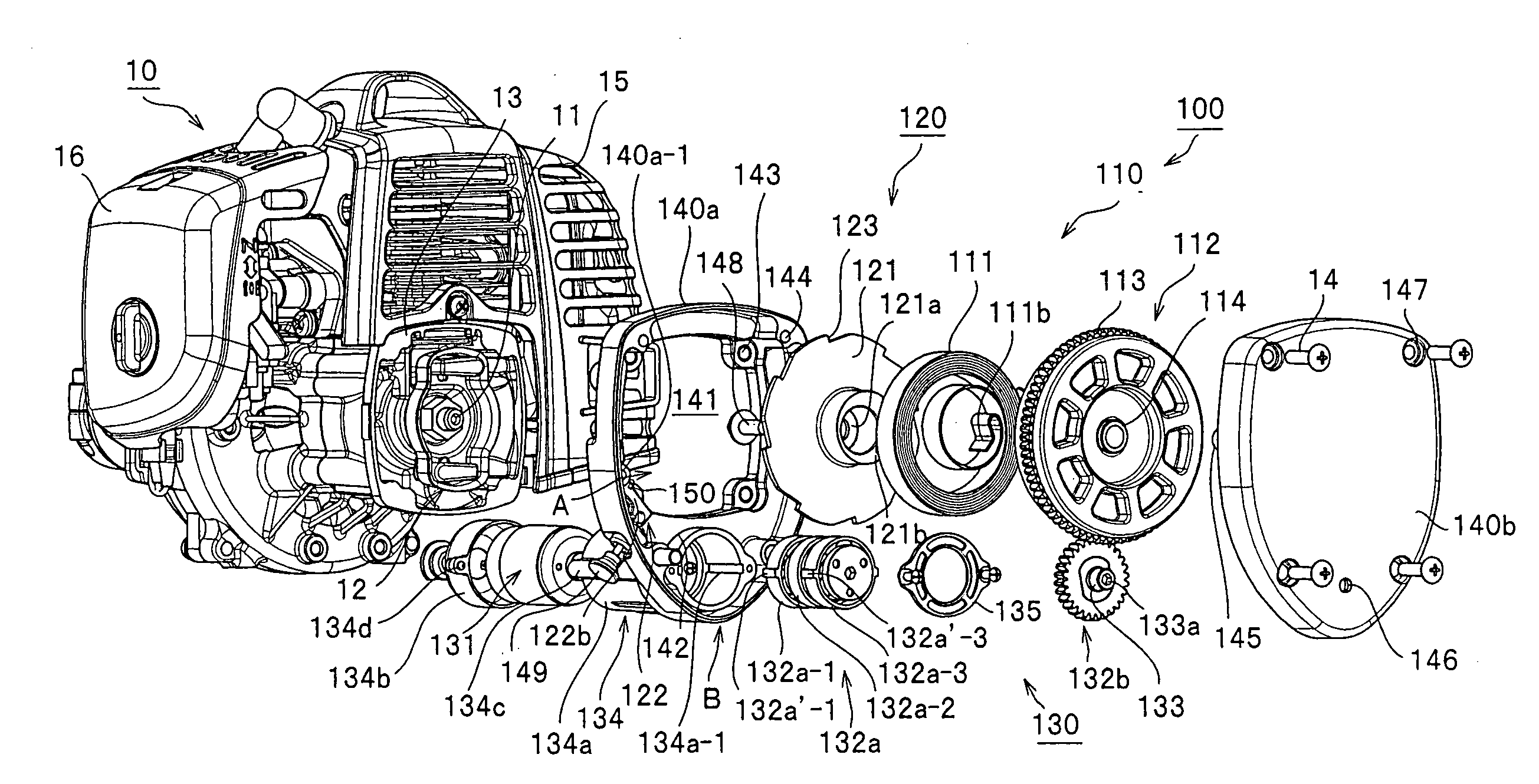
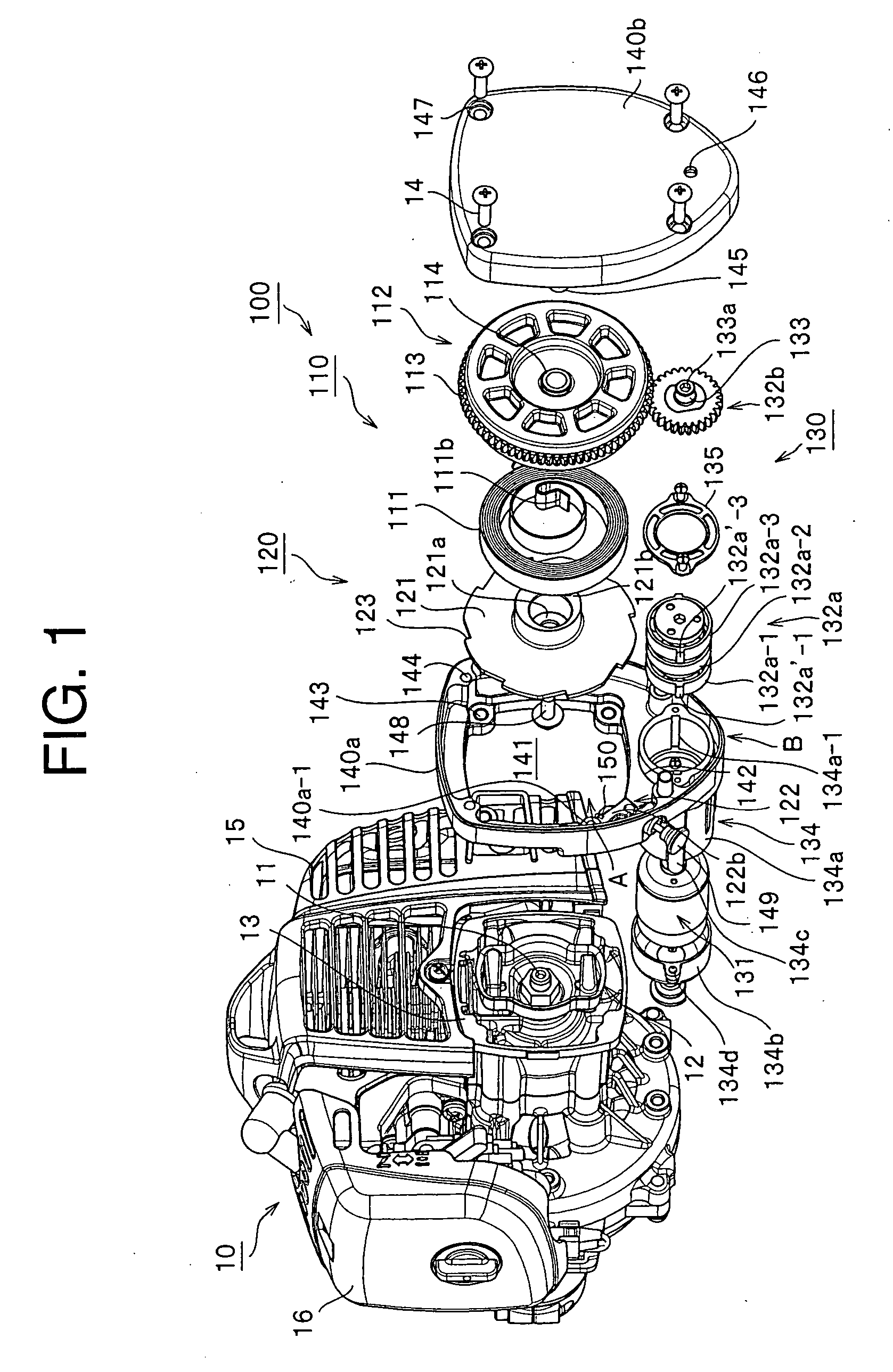
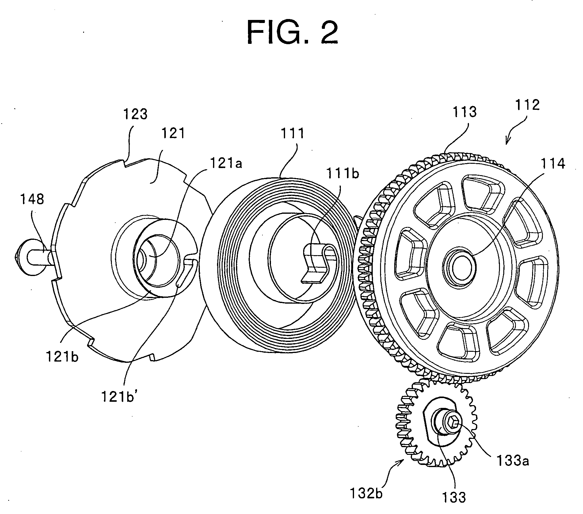
[0040]FIG. 1 is an exploded view of an electric engine starter showing the first embodiment of the invention and an internal combustion engine at a stage of their assembly. FIG. 2 to FIG. 5 are views for use in describing the arrangement and the structure of each component of the engine starter in the first embodiment. The engine starter 100 of the invention is used for a compact air-cooled 2-cycle gasoline engine and the starter 100 is arranged near by an input end of a crankshaft 11 of the internal combustion engine 10.

[0041] The engine starter 100 includes a power accumulating unit 110, a power transmission unit 120, and an electric driving unit 130, and they are integrated together and accommodated in a single case 140. The case 140 has a rectangular-shaped first space A for accommodating the power accumulating unit 110 and the power transmission unit 120 in...


PUM


Abstract

An electric engine starter in which downsizing and weight saving are improved to an extreme based on the rational design and by eliminating an unnecessary unit, wherein a battery is arranged outside the starter, a power accumulating unit has a rotation supporting unit for supporting one end of a spring, a first gear is formed on the rotation supporting unit, a second gear is fixed to an output shaft of a high-speed reduction gear mechanism, the first and the second gears are engaged with each other, the power accumulating unit and the power transmission unit are arranged on the same first axis line, the compact electric motor and the high-speed reduction gear mechanism are arranged on the same second axis line parallel to the first axis line, and the first axis line and the second axis line are arranged on the same plane surface.

Description

BACKGROUND OF THE INVENTION [0001] 1. Field of the Invention [0002] The present invention relates to an engine starter which starts an internal combustion engine by using an ultra-compact direct current motor, and more particularly to an electric engine starter which can remove a conventional recoil driving unit from its body and arrange a battery for driving the motor, outside there, hence to realize downsizing because of the most efficient arrangement of the components and to extremely decrease fatigues at each operation of various working machine. [0003] 2. Description of the Related Art [0004] At the present, an engine starter which starts a compact air-cooled gasoline engine mounted on a popular portable machine such as a shearing machine and a chain saw generally includes a recoil driving unit, a follower connected to a crank shaft of an engine through an switching means such as a centrifugal clutch, and a shock absorbing / pressure accumulating unit including a spring, arranged...

Claims


Application Information

Patent Timeline
IPC IPC(8): F02N11/00F02N5/02
CPCF02N5/02F02N15/066F02N15/022F02N15/006
Inventor ONO, RYOU
Owner HUSQVARNA ZENOAH
Learn More