Method and apparatus for increasing filter contaminant loading capacity

a filter and contaminant technology, applied in gravity filters, loose filtering materials, stationary filtering elements, etc., can solve the problems of increased resistance of the bed, increased pressure drop, and increased flow, so as to reduce the amount of time the filter is out of service, reduce the ripening time and volume of filtrate, and increase the solids loading capacity of the filter

Active Publication Date: 2006-02-09
ECO TEC INC
View PDF7 Cites 18 Cited by
  • Summary
  • Abstract
  • Description
  • Claims
  • Application Information

AI Technical Summary

Benefits of technology

[0026] An important aspect of the invention is that the upper, coarse media layer is not expanded during the back-slip. As a result, no significant quantities of solids are removed from this layer. If the upper, coarse layer were allowed to expand, appreciable quantities of solids would be dislodged from the media and they would pass into the freeboard. If they are not flushed from the filter vessel, they would immediately deposit on the top of the filter bed when the filter is returned to service. This would have two deleterious effects: First of all, because the solids would have been previously agglomerated on the media, they would not penetrate deeply into the bed and would tend to form a continuous layer of low permeability on top of the media bed similar to the ‘crust’ described above, that occurs with single layer filters of the prior art. This would cause high initial pressure drop and reduce the length of time before the filter must be taken out of service again. Under these conditions, the initial pressure drop could actually be higher than the pressure drop across the filter before the back-slip. The other deleterious effect is that this layer of solids would become compressed during service and could lead to the formation of mud-balls, as described above.
[0034] It has been found that the use of a fine media layer whose particle size is less than 25% of the diameter of the coarse layer, has additional advantages. Specifically, it appreciably reduces the ripening time and volume of filtrate that must be diverted to waste. Consequently, the, amount of additional filtrate produced after a back-slip that is acceptable before necessitating a backwash can be rather small. In other words, because of the short ripening period afforded by using finer media, more back-slips can be performed before a backwash is necessary, thereby increasing the solids loading capacity of the filter and reducing the amount of time the filter is out of service.

Problems solved by technology

At the same time, the flow resistance of the bed increases and the flow may become too slow and / or the pressure drop may become too high.
On the other hand, a higher service liquid velocity generally causes increased leakage of solids into the filtrate.
The disadvantage of reducing the media particle size is that a larger proportion of the solids will be filtered on the top surface of the filter media bed instead of penetrating deeper into the media bed.
As a result, pressure drop across the filter increases very quickly or the flow drops very rapidly.
This results in prohibitively short filter runs between backwashes.
The disadvantage of using coarse media is that the solids removal efficiency is inferior to fine media beds.
Even under optimal conditions however, such filters typically undergo a ripening period when they are first put into service after a backwash.
During this period, water quality is inferior and must be discarded.
Depth media filters are limited in their solids loading capacity.
Furthermore, the amount of time devoted to backwashing also becomes more significant as [TSS] increases.
Eventually, feed [TSS] reaches a point where it is no longer feasible to use a filter of this type.
As a result, the service cycle may be relatively short.
In some cases, these fragments are so large and dense that they cannot be removed from the filter during backwash.
Mudballs can accumulate in the filter media bed and eventually interfere with filtration operation and efficiency.

Method used


Image

  • Method and apparatus for increasing filter contaminant loading capacity
  • Method and apparatus for increasing filter contaminant loading capacity
  • Method and apparatus for increasing filter contaminant loading capacity

Examples


example

[0038] A dual media filter of a preferred embodiment of the invention was assembled for testing with the following specifications: [0039] Vessel diameter: 16 inches (40.6 cm) [0040] Vessel height: 96 inches (244 cm) [0041] Top media material: anthracite [0042] Top media density: 1.5 g / cm3 [0043] Top media effective size: 0.69 mm [0044] Top media unexpanded / free settled height: 36 inches (91 cm) [0045] Bottom media material: zircon sand [0046] Bottom media density: 4.6 g / cm3 [0047] Bottom media effective size: 0.09 mm (the ratio of fine to coarse particle size=0.13) [0048] Bottom media unexpanded / free settled height (above bottom strainers): 8 inches (20 cm)

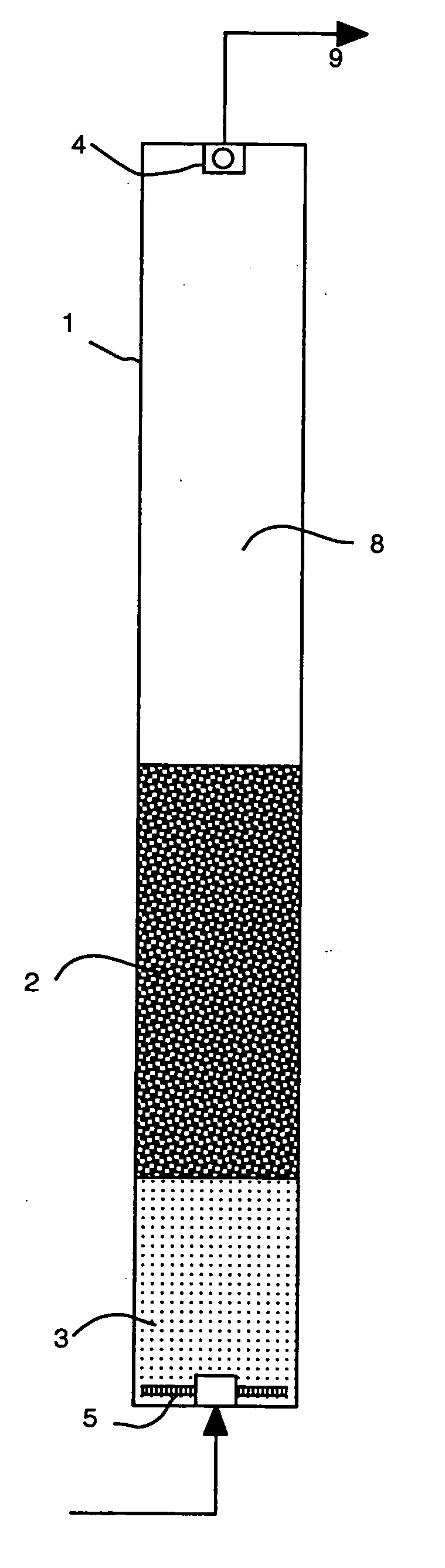
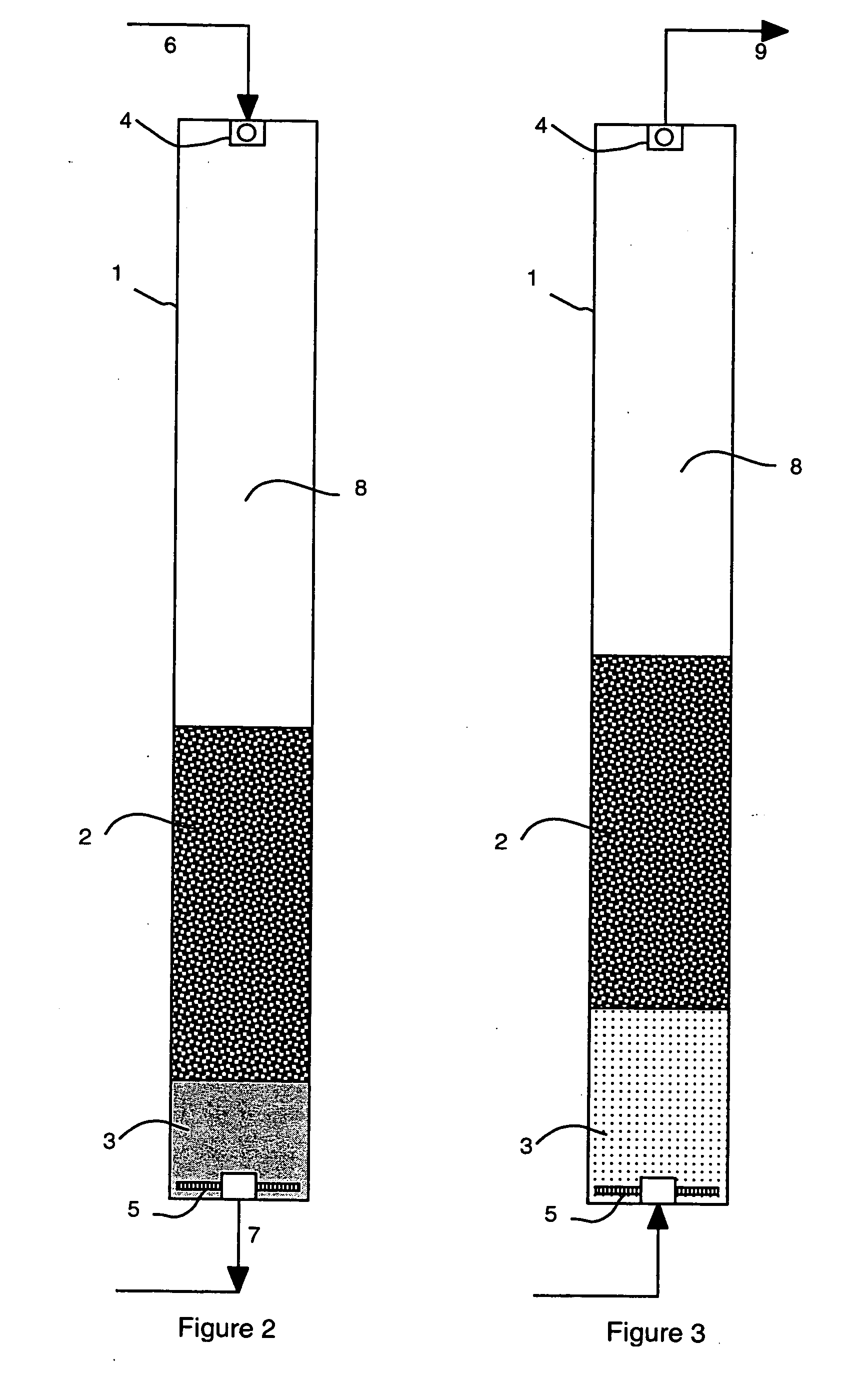
[0049] The filter is shown in FIG. 2 and includes a pressure vessel (i.e. the filter vessel) 1 containing two layers of filter media, consisting of an upper, coarse media layer 2 and a lower, fine media layer 3. Liquid to be treated 6 is admitted to the top of the filter vessel 1. A fluid distributor 4 is used to dissipate the in...


PUM

PropertyMeasurementUnit
depthaaaaaaaaaa
velocitiesaaaaaaaaaa

Abstract

The filter contaminant loading capacity of a depth granular. media filter is increased by imposing a so-called “back-slip” on the filter bed. At intervals between normal backwashing, a volume of liquid is passed upwardly through the media bed under flow conditions selected to displace at least some of the contaminants upwardly in the bed while essentially removing none of the contaminants from the filter vessel. Preferably, the filter bed comprises at least two media types of different but uniform particle sizes and densities, the media types each forming a distinct layer in which the effective particle size of the media in each successive layer decreases in a downward direction in the vessel.

Description

FIELD OF THE INVENTION [0001] This invention relates generally to so-called depth granular media filters such as sand filters. BACKGROUND OF THE INVENTION [0002] Filters of this type have long been used to purify liquids such as water and wastewater of contaminants. The contaminants removed by these filters are undissolved and may be solids or immiscible liquids such as oil. For simplicity, the term ‘solids’ will be used herein and is intended to include immiscible liquid contaminants and solid contaminants. The simplest configuration consists of a single layer or bed of granular media such as silica sand, 30-100 cm in depth, contained within a containment means or vessel. The liquid to be filtered flows downward through the media bed under the influence of gravity or applied pressure. [0003] As the service cycle proceeds, solids accumulate on the surface and within the media bed, in the interstices of the media particles. Solids are driven further into the media bed over time and e...

Claims


Application Information

Patent Timeline
Patent Type & Authority Applications(United States)
IPC IPC(8): B01D24/46
CPCB01D24/007B01D24/4631
Inventor BROWN, CRAIG J.SHEEDY, MICHAEL A.
Owner ECO TEC INC
Why Eureka
Try Eureka