
Traveling wave tube with radioactive isotope charged particle source

Inactive Publication Date: 2006-02-09
L 3 COMM ELECTRON TECH
View PDF3 Cites 8 Cited by
  • Summary
  • Abstract
  • Description
  • Claims
  • Application Information

AI Technical Summary

Benefits of technology

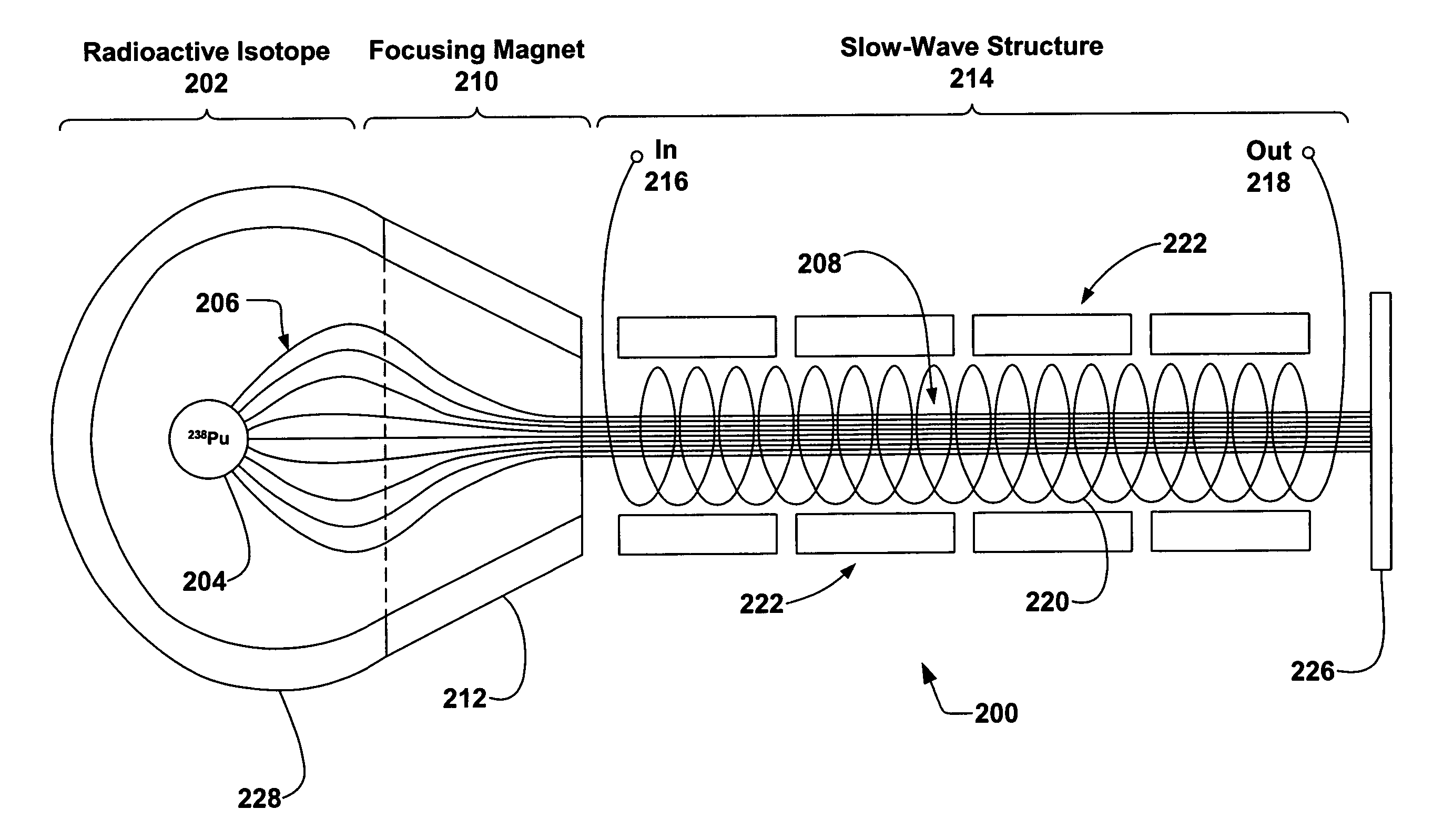
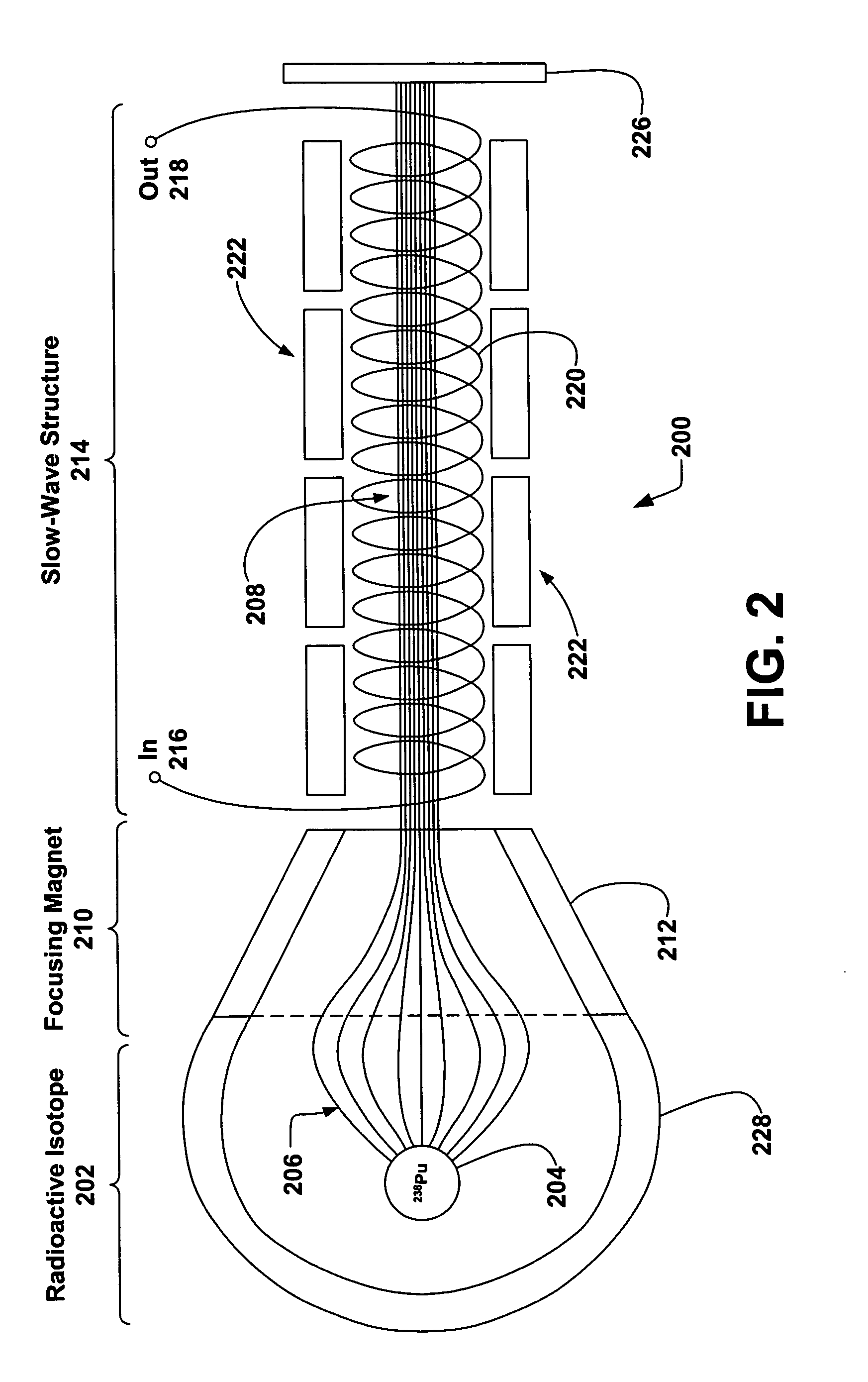
[0012] This invention presents a system and method for mediating electromagnetic interaction with an RF wave in a TWT. Embodiments of the present invention can be employed in high power amplifiers in satellite transponders or radar systems. Embodiments of the invention extract RF power directly from a radioactive isotope (e.g. 238Pu) by implementing a slow-wave structure in conjunction with the charged particles (e.g. alpha particles) from the isotope. In satellite applications, the invention can significantly reduce costs and mass by dramatically reducing the requirements of the supporting electrical power system.
[0013] Typical embodiments of the invention comprise a particle traveling wave tube employing a simple, long lasting radioactive isotope as a charged particle source. Embodiments of the invention may dramatically reduce or eliminate the need for a bulky high voltage power system and solar panels in a conventional satellite communication system. For example, alpha particles from 238Pu can be channeled through a cylindrical slow-wave structure and undergo a charge-wave interaction. The alpha particles gradually lose their kinetic energy via charge-wave interaction, thereby transferring their kinetic energy to the coupled wave. The alpha particles' large mass to charge ratio makes such and alpha TWT more linear than the conventional electron TWT. In addition, the high RF conversion efficiency of the alpha TWT makes such a device an attractive alternative for a radioisotope thermoelectric generator (RTG) used in deep space missions.

Problems solved by technology

In a typical satellite, even with efficient TWTs, the HPAs may consume more than ninety percent of the available D.C. power.
These components are expensive and consume a significant portion of the mass budget.
For example, the solar arrays and batteries for a typical communications satellite may cost ten million dollars and weigh a thousand pounds.

Method used


Image

  • Traveling wave tube with radioactive isotope charged particle source
  • Traveling wave tube with radioactive isotope charged particle source
  • Traveling wave tube with radioactive isotope charged particle source

Examples


Embodiment Construction

[0027] In the following description of the preferred embodiment, reference is made to the accompanying drawings which form a part hereof, and in which is shown by way of illustration a specific embodiment in which the invention may be practiced. It is to be understood that other embodiments may be utilized and structural changes may be made without departing from the scope of the present invention.

1. Conventional Traveling Wave Tube

[0028] Having been around more than a half century, the basic principle of the traveling wave tube (TWT) is well understood. Many variants and modifications have developed over the years to improve and alter performance characteristics, however, the fundamental operation remains unchanged.

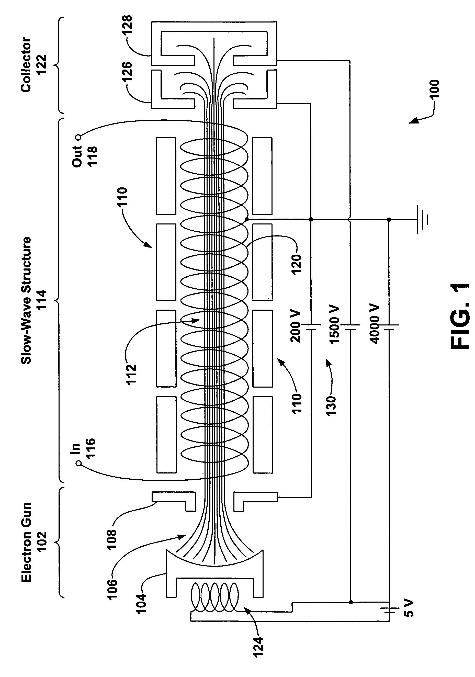
[0029]FIG. 1 illustrates a conventional TWT 100. The TWT 100 is cylindrical in shape, employing the electron gun 102 near one end generating a stream of electrons 106 that are expelled thermionically from a cathode 104 due to an electric heater 124. The electrons 106...


PUM


Abstract

The invention discloses systems and methods for mediating electromagnetic interaction with an RF wave in a TWT. Embodiments of the present invention can be employed in high power amplifiers in satellite transponders or radar systems. Embodiments of the invention extract RF power directly from a radioactive isotope (e.g. 238Pu) by implementing a slow-wave structure in conjunction with the charged particles (e.g. alpha particles) from the isotope. In satellite applications, the invention can significantly reduce costs and mass by dramatically reducing the requirements of the supporting electrical power system.

Description

BACKGROUND OF THE INVENTION [0001] 1. Field of the Invention [0002] The present invention relates to systems and methods for mediating an electromagnetic interaction with a radio frequency (RF) wave in a traveling wave tube (TWT). Particularly, this invention relates to systems and methods for amplifying an RF wave in a TWT that can be employed in a high power amplifier such as used in communications and radar systems. [0003] 2. Description of the Related Art [0004] The traveling wave tube (TWT) is an amplifier (also referred to as a traveling wave tube amplifier (TWTA)) of microwave energy, operating through the interaction of an electron beam and an RF circuit known as a slow-wave structure (SWS). The term “slow-wave” comes from the fact that the RF wave velocity as it travels down the circuit is much less than that of light in free-space. As the electron beam travels down the slow-wave structure an energy exchange takes place between the particles and the RF circuit wave. [0005] ...

Claims


Application Information

Patent Timeline
IPC IPC(8): H01J25/34
CPCH01J25/34
Inventor CHUN, SEBONG
Owner L 3 COMM ELECTRON TECH
Learn More