
Lighting apparatus for illumination light source

a technology for lighting apparatuses and light sources, applied in the direction of electric variable regulation, process and machine control, instruments, etc., can solve the problems of increasing the cost and similar associated with the setting, affecting the accuracy of setting the fluctuation width of the target power in the design, and affecting the accuracy of setting the target power, etc., to achieve the effect of preventing electromagnetic interference, sufficient suppression of harmonic noise, and preventing electromagnetic interferen

Inactive Publication Date: 2006-02-09
KOITO MFG CO LTD
View PDF7 Cites 18 Cited by
  • Summary
  • Abstract
  • Description
  • Claims
  • Application Information

AI Technical Summary

Benefits of technology

[0017] Therefore, fluctuations can be given to the switching frequency, and the width of the fluctuations can be accurately set in design as a result by manipulating the supplied power value on the assumption that fluctuations are allowed upward and downward, centered at a target power value associated with the power control for the illumination light source.
[0019] According to the invention, it is possible to appropriately give fluctuations to the switching frequency to sufficiently suppress harmonic noise, thus substantially preventing electromagnetic interference.
[0020] The control circuit comprises an error processing unit, and a control signal generator for generating a control signal to the switching element. The error processing unit is supplied with a reference signal as one input signal, and with an output signal of the fluctuation generator circuit multiplexed on a power control signal calculated based on information on a detected voltage or current of the illumination light source as another input signal. In this way, it is possible to take measures to noise without more complicated circuit configuration and control, and / or a significant increase in cost.
[0021] In comparison with a method of multiplexing an output signal of a fluctuation generator circuit on a reference signal of an error processing unit, it is possible to control frequency fluctuations with stability against various factors associated with the manufacturing of the error processing unit, variations in characteristics, changes in temperature, and the like.

Problems solved by technology

However, when constant power is applied to a discharge lamp, the switching frequency is uniquely determined, and the harmonics of the switching frequency exert a problematic influence (radio noise) on a radio broadcasting band.
However, in the related art circuit configurations, problems arise in terms of the difficulties of accurately setting a fluctuation width for target power in design.
Further, in a more complicated configuration, there is an increase in cost and the like associated with the setting.
In this event, unless the fluctuation width is not appropriately set, the noise level cannot be sufficiently reduced, thus requiring countermeasures through additional provision of a noise filter, leading to an increase in the number of parts and the cost.

Method used


Image

  • Lighting apparatus for illumination light source
  • Lighting apparatus for illumination light source
  • Lighting apparatus for illumination light source

Examples


Embodiment Construction

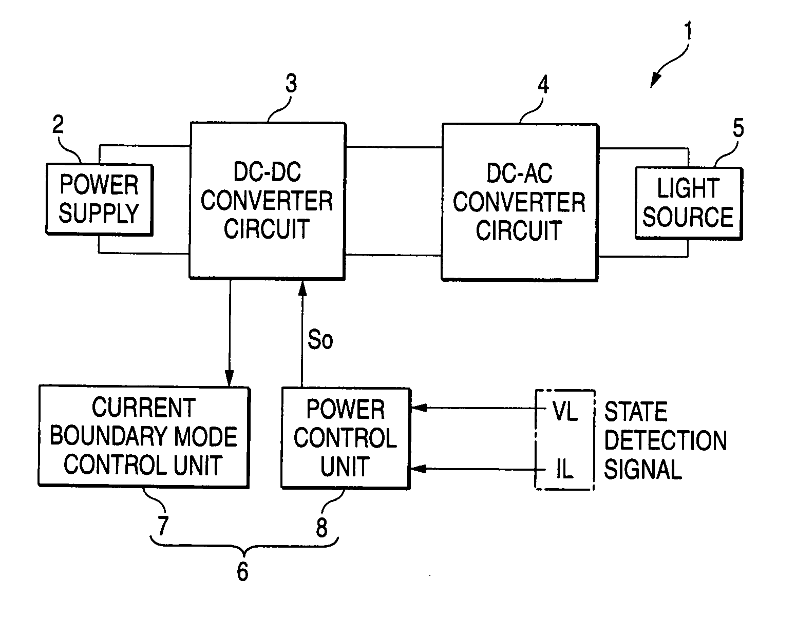
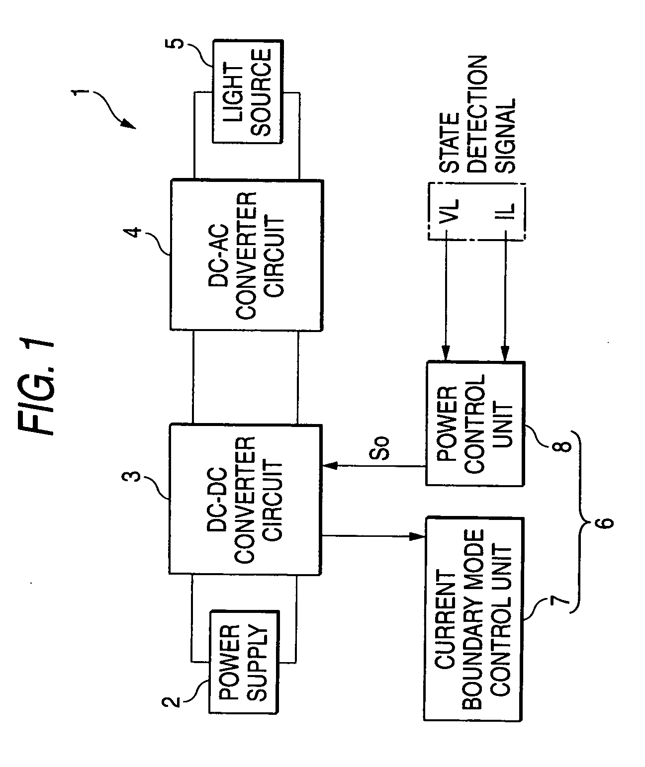
[0026]FIG. 1 illustrates an exemplary, non-limiting configuration of a discharge lamp lighting apparatus 1. A DC-DC converter circuit 3 coupled to a DC power supply 2 receives a DC input voltage from the DC power supply 2 for conversion to a desired DC voltage. A fly-back type DC-DC converter is used for the DC-DC converter circuit 3. As described further below, in a circuit configuration having a transformer and a switching element, the switching element is driven by a control signal from a control circuit.

[0027] A DC-AC converter circuit 4 is provided for converting an output voltage of the DC-DC converter circuit 3 to an AC voltage and supplying the converted AC voltage to an illumination light source 5 (discharge lamp such as an HID lamp). For example but not by way of limitation, in a circuit configuration of H-bridge (or full bridge), four semiconductor switches are used to make up two arms, and driving circuits are included for driving the switching elements on the respectiv...


PUM


Abstract

In a lighting apparatus for an illumination light source (discharge lamp or the like), a fly-back type DC-DC converter circuit comprises a transformer and a switching element. A control circuit is provided for controlling power supplied to the illumination light source, such that operation is controlled in a current boundary mode by a control signal sent from the control circuit to the switching element. A fluctuation generator circuit is provided for giving fluctuations to a frequency at which the switching element is driven by changing the power supplied to the illumination light source with reference to a target power value associated with the power control for the illumination light source.

Description

[0001] The present invention claims foreign priority, based on Japanese patent application no. JP2004-229376, filed on Aug. 5, 2004, the contents of which is incorporated herein by reference in its entirety. This priority claim is being made concurrently with the filing of this application. BACKGROUND [0002] 1. Technical Field [0003] The present invention relates to noise prevention techniques in a lighting apparatus which uses a fly-back type DC voltage converting means. [0004] 2. Related Art [0005] When a discharge lamp (HID lamp or the like) or a light emitting element (LED or the like) is used for car illumination, a related art switching power supply circuit (DC-DC converter) is employed for controlling the power of the light source. For example, in a related art fly back scheme which employs a transformer, a semiconductor switching element such as an FET arranged on the primary side of the transformer, there are three operation modes as shown below: [0006] Current Continuous M...

Claims


Application Information

Patent Timeline
Patent Type & Authority Applications(United States)
IPC IPC(8): H05B37/02H02M3/335H05B41/282H05B44/00
CPCH02M3/33507H05B41/282H05B33/0815H05B45/382Y02B20/00H05B45/385H05B41/2824H05B45/37
Inventor ICHIKAWA, TOMOYUKISUZUKI, TOMOKAZU
Owner KOITO MFG CO LTD
Learn More