Envelope detection circuit for low power communication systems

a low-power communication system and detection circuit technology, applied in the field of envelope detection circuitry, can solve the problems of large capacitors occupying a significant amount of space, ripples on the rectified supply vdd can be detrimental to the functioning of the rfid tag circuitry, and large capacitors affecting the operation of the circuit, so as to achieve high demodulated signal fidelity and low power consumption

Inactive Publication Date: 2006-02-09
AGENCY FOR SCI TECH & RES
View PDF7 Cites 13 Cited by
  • Summary
  • Abstract
  • Description
  • Claims
  • Application Information

AI Technical Summary

Benefits of technology

[0009] The present invention provides an envelope detection circuit which is optimized for high demodulated signal fidelity and low power consumption. The described circuitry may be employed in any system having such requirements, and has particular applicability in applications such as RFID circuitry in which minimal power consumption is required.

Problems solved by technology

By sharing the same radio field with the communication channel, the ASK / OOK modulation scheme results in ripples on the power rectified output.
Ripples on the rectified supply VDD can be detrimental to the functioning of the RFID tag circuitry.
However, a large capacitor would take up a significant amount of space, and if fabricated on an integrated circuit, would consume a significant amount of area and decrease IC yield.
Decreasing the modulation index requires complex demodulation circuitry, and would be sensitive to environmental perturbations.
Power consumption of such envelope detector becomes a major concern as data rate or duty ratio increases.

Method used


Image

  • Envelope detection circuit for low power communication systems
  • Envelope detection circuit for low power communication systems
  • Envelope detection circuit for low power communication systems

Examples


Embodiment Construction

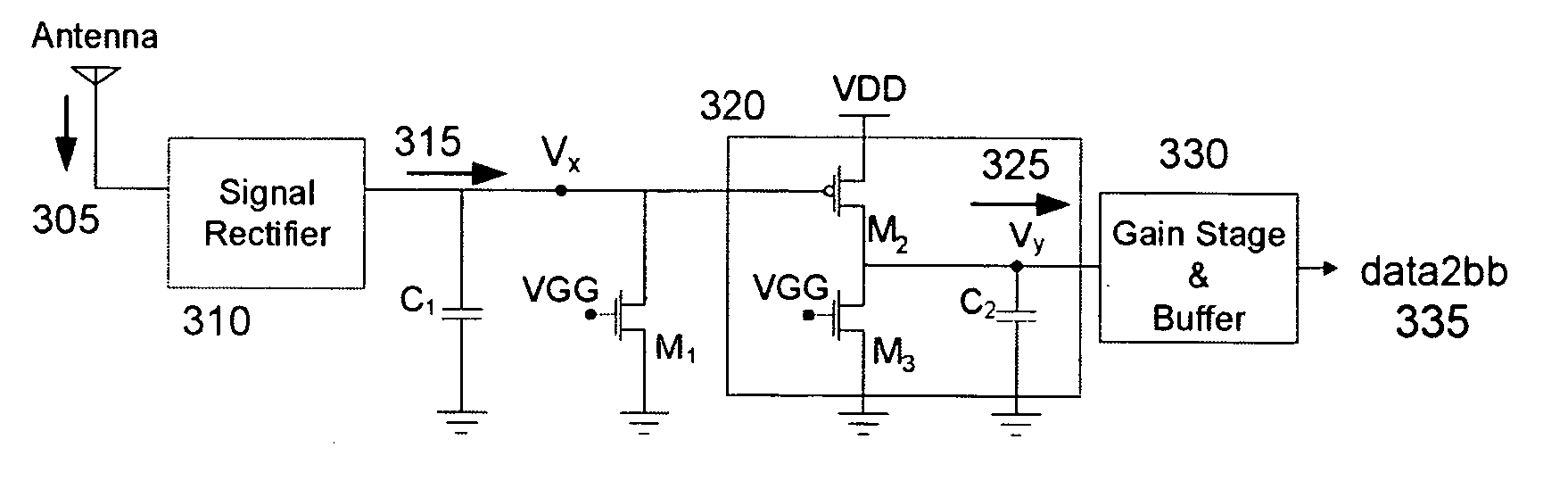
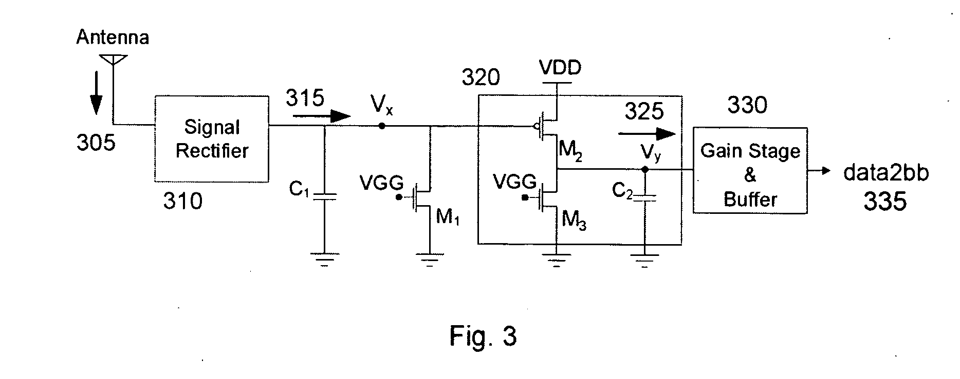
[0016] As an exemplary embodiment, the envelope detection circuit of the present invention is now illustrated in terms of an RFID receiver. Those skilled in the art will appreciate that the envelope detection circuit is not limited to this particular application, but may be employed in a variety of amplitude modulated receivers in which minimal power consumption is desired.

[0017]FIG. 3 illustrates an envelope detection circuit in accordance with the present invention. Shown are the modulated signal 305 at the input, the rectified signal Vx 315, the compensated signal Vy 325, and the demodulated baseband signal data2bb 335. The envelope detection circuit includes a signal rectifier 310, first and second capacitors C1 and C2, and first, second and third transistors M1, M2, and M3. The signal rectifier 310 may include one or more diodes, diode-connected transistors, or other signal rectifier means. In a particular embodiment, capacitors C1 and C2, and transistors M1, M2, and M3 are mo...


PUM


Abstract

An envelope detection circuit includes a signal rectifier, first and second capacitors, and first, second and third transistors. The signal rectifier includes an input port coupled to receive a modulated input signal, and an output port. The first capacitor has a first port coupled to the output port of the signal rectifier and a second port for coupling to a signal ground. The first transistor has a first port coupled to the output port of the signal rectifier, a second port for coupling to a signal ground, and a control port. The second transistor has a first port for coupling to a power supply, a second port, and a control port coupled to the output of the signal rectifier. The third transistor has a first port coupled to second port of the second transistor, a second port for coupling to a signal ground, and a control port. The second capacitor has a first port coupled to first port of the third transistor, and a second port for coupling to a signal ground.

Description

BACKGROUND [0001] The present invention relates to envelope detection circuitry, more particularly to envelope detection circuitry for use in low power communication devices employing amplitude modulation scheme. [0002] Low power, high fidelity amplitude modulated receivers are used in numerous systems, such as portable AM radio receivers, two way radios, and remote control devices, telemetry radios and the like. Such portable devices typically operate on very little power in order to extend their usage, and accordingly require minimal power consumption during both signal demodulation and standby mode operation when no input signal is detected. [0003] Radio frequency identification (RFID) represents another system in which amplitude modulated signals are used to remotely communicate information. As known in the art, RFID systems can be used in asset tracking and inventory management systems in which RFID tags (i.e., small RFID transceivers) may be place on an asset, and the asset's ...

Claims


Application Information

Patent Timeline
Patent Type & Authority Applications(United States)
IPC IPC(8): G08B13/14
CPCG06K19/07786G06K19/0723
Inventor CHOI, YEUNG BUNYEOH, WOOI GAN
Owner AGENCY FOR SCI TECH & RES
Why Eureka
Try Eureka