
Digital communications transmitter with synthesizer-controlled modulation and method therefor

a digital communication and transmitter technology, applied in the field of low-power digital communication transmitters, can solve the problems of increasing the cost of exotic batteries, requiring more expensive and heavy batteries, and requiring faster battery draining, and achieve the effect of significant power-consuming components

Inactive Publication Date: 2006-02-09
GENERAL DYNAMICS C4 SYSTEMS
View PDF6 Cites 13 Cited by
  • Summary
  • Abstract
  • Description
  • Claims
  • Application Information

AI Technical Summary

Benefits of technology

[0008] Accordingly, it is an advantage of the present invention that an improved digital communications transmitter with synthesizer-controlled modulation and method are provided.
[0009] Another advantage of the present invention is that pulse-shaping and IF / RF modulation functions are combined.
[0010] Another advantage of the present invention is that a digital synthesizer is controlled to provide both IF / RF modulation and pulse shaping.
[0011] Yet another advantage of the present invention is that the significant power-consuming components can be limited to a high-power amplifier (HPA) and two semiconductor devices.
[0012] These and other advantages of the present invention are carried out in one form by a digital communications transmitter which includes a digital-processing circuit configured to generate a digitally-modulated symbol for each unit interval. A frequency-profiling circuit is configured to generate a plurality of digitally-specified frequencies per unit interval in response to each digitally-modulated symbol. The digitally-specified frequencies are arranged so as to confine radio-frequency (RF) emissions within a predetermined spectral mask. A digital synthesizer has a frequency input that couples to the frequency-profiling circuit and has a periodic output. The periodic output of the digital synthesizer couples to a digital-to-analog converter.

Problems solved by technology

Greater power consumption causes batteries to drain faster.
Consequently, either larger or heavier batteries must be used, or more expensive and exotic batteries must be used.
On the other hand, when power consumption can be reduced, smaller batteries may be used to reduce the size and weight of the transmitter, or a longer operating time results from maintaining a constant battery size.
Linear amplifiers tend to be less efficient (i.e., to consume more power for a given broadcast signal level) and to be more expensive.
Moreover, in order to minimize spectral regrowth, linear amplifiers either tend to be operated at large backoff, where they are particularly inefficient, or to be designed with expensive and power-hungry linearization circuits.
But conventional digital communications transmitters that have low power consumption as a primary focus pay scant attention to the digital and analog signal processing taking place upstream of the power amplifier.
Consequently, such processing tends to be conducted in a manner that leads to undesirable power consumption.
But such a filter uses a significant number of processing circuits and often necessitates an increase in clock rate, so that in many cases at least twice the amount of data needs to be processed within a given block of time in the pulse-shaping filter and all digital circuits downstream of the pulse-shaping filter.
Thus, the conventional pulse-shaping filter increases power consumption both in the filter itself and downstream of the filter.
But the use of FPLA's still causes excessive power consumption because different parts of the chip typically cannot be managed differently for power consumption purposes.
Inefficient power management results.
And, conventional digital communications transmitters that have low power consumption as a primary focus tend to provide separate circuits of significant complexity for pulse-shaping and for intermediate frequency (IF) or RF modulation.
This practice leads to the inclusion of additional data processing and / or processing circuits and again results in increased power consumption.

Method used


Image

  • Digital communications transmitter with synthesizer-controlled modulation and method therefor
  • Digital communications transmitter with synthesizer-controlled modulation and method therefor
  • Digital communications transmitter with synthesizer-controlled modulation and method therefor

Examples


Embodiment Construction

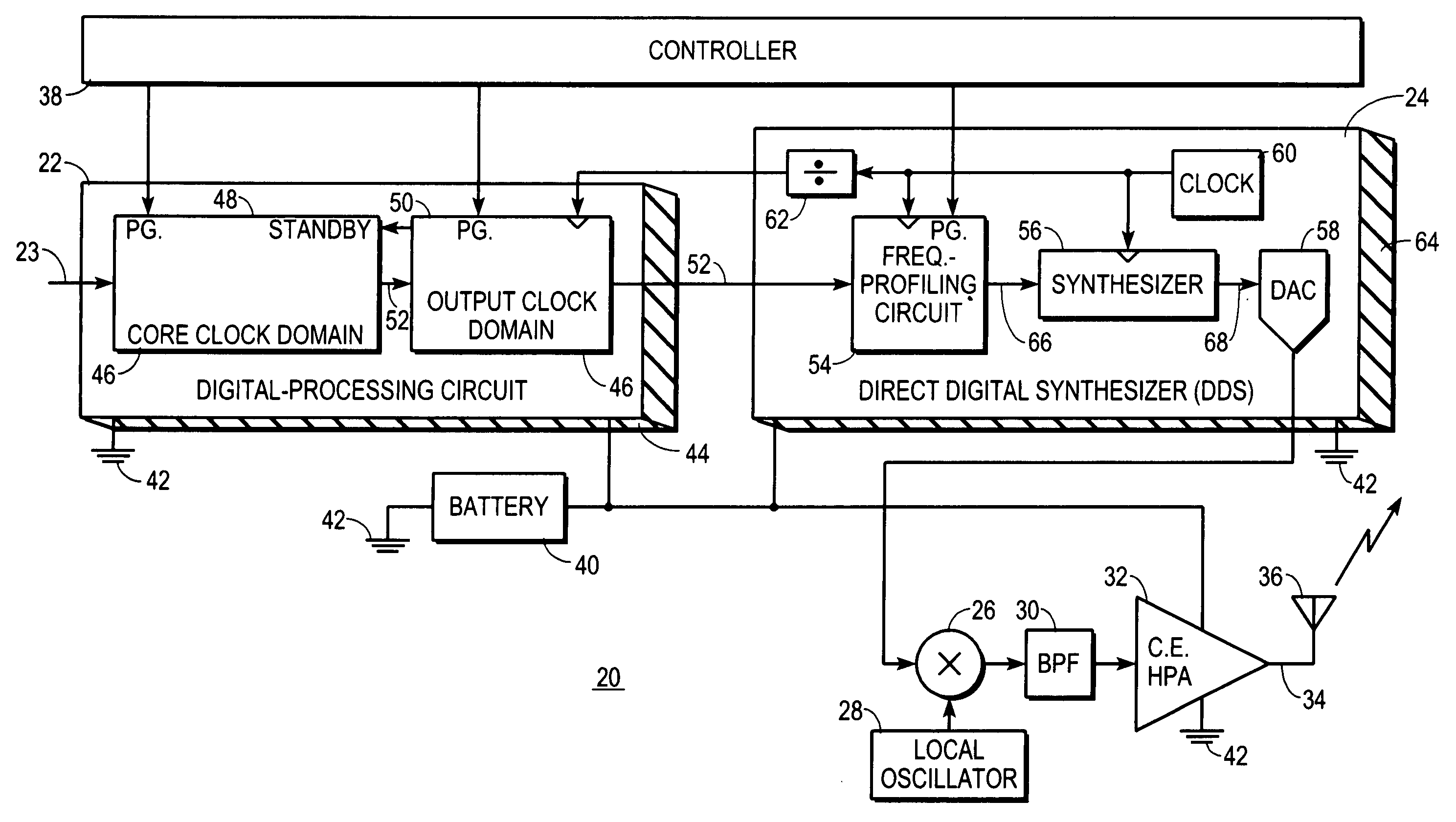
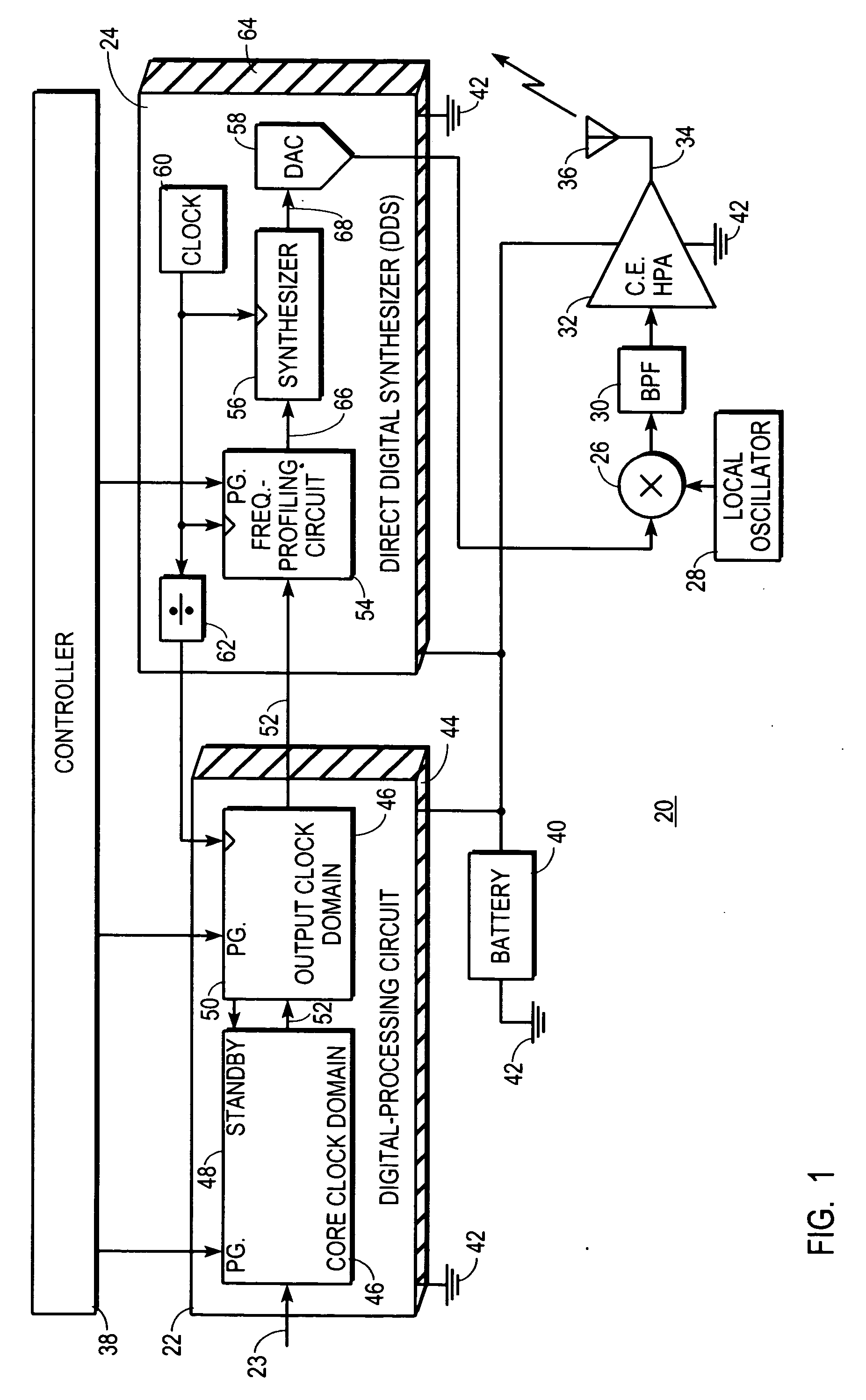
[0023]FIG. 1 shows a block diagram of a digital communications transmitter 20 configured in accordance with one embodiment of the present invention. Transmitter 20 includes a digital-processing circuit 22, which receives the payload data to be communicated from transmitter 20 at an input port 23, and a direct digital synthesizer (DDS) 24, which performs pulse-shaping and which performs at least modulation of an intermediate-frequency (IF) carrier, and possibly modulation of a radio-frequency (RF) carrier. DDS 24 couples to digital-processing circuit 22 in a manner discussed in more detail below.

[0024] In the preferred embodiment, if the carrier frequency is less than a few hundred MHz, then an analog output from DDS 24 can serve as an RF carrier signal. When the carrier frequency is more than a few hundred MHz, then the analog output from DDS 24 is an IF signal that couples to a first input of a mixer 26. A second input of mixer 26 couples to an output from a local oscillator 28, a...


PUM


Abstract

A low-power digital communications transmitter (20) includes a programmable digital-processing circuit (22), which may be provided by a digital signal processor (DSP), a programmable direct digital synthesizer (DDS), and a constant-envelope, high power amplifier (32). The DDS (24) is programmed to provide pulse-shaping and IF / RF signal modulation functions. The digital-processing circuit (22) produces only one sample per unit interval (134) and is programmed so that the one sample per unit interval (134) is a frequency-profile index symbol (52″) produced from a I,Q baseband symbol (52′). The DDS (24) converts each frequency-profile index symbol (52″) into a frequency profile (130) that controls the frequency of a synthesizer (56) to induce modulation into a periodic output (68) of the synthesizer. Moreover, the frequency profile (130) is configured to confine spectral emissions within a spectral mask (140).

Description

TECHNICAL FIELD OF THE INVENTION [0001] The present invention is related to low-power, digital-communications transmitters. BACKGROUND OF THE INVENTION [0002] Reducing power consumption in radio-frequency (RF) transmitters is always a desirable goal. But in some applications low power consumption is more important than merely being a desirable goal. For example, in battery-powered applications, low power consumption is more important. Greater power consumption causes batteries to drain faster. Consequently, either larger or heavier batteries must be used, or more expensive and exotic batteries must be used. On the other hand, when power consumption can be reduced, smaller batteries may be used to reduce the size and weight of the transmitter, or a longer operating time results from maintaining a constant battery size. [0003] In some battery-powered applications, low power consumption is still even more important than in others. For example, where small size and / or low weight are req...

Claims


Application Information

Patent Timeline
IPC IPC(8): H04L27/20
CPCH04L27/2092
Inventor KOST, ROBERT ROYWALDO, MICHAEL KIP EUGENETORELL, KENT LYNN
Owner GENERAL DYNAMICS C4 SYSTEMS
Learn More