
Leakproof zipper end crush for reclosable bag and related method of manufacture

a reclosable bag and zipper end technology, applied in envelope/bag making machinery, flexible container closures, paper/cardboard containers, etc., can solve the problems of affecting the sealing effect of the zipper mouth, affecting the sealing effect of the bag, etc., to achieve sufficient ultrasonic wave energy

Active Publication Date: 2006-02-09
ILLINOIS TOOL WORKS INC
View PDF1 Cites 36 Cited by
  • Summary
  • Abstract
  • Description
  • Claims
  • Application Information

AI Technical Summary

Benefits of technology

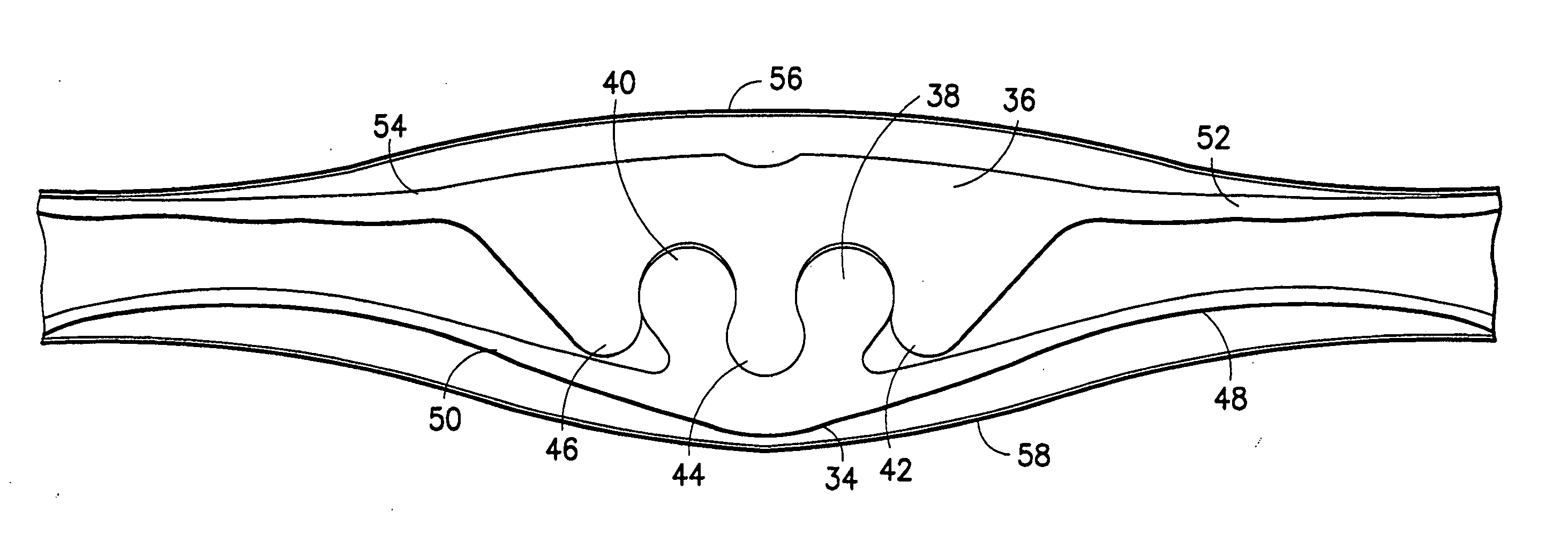
[0010] One aspect of the invention is a method of forming a zipper joint joining first and second zipper strips made of thermoplastic material, wherein the first zipper strip comprises a first base and a first longitudinal closure element projecting from the first base, and the second zipper strip comprises a second base and second and third longitudinal closure elements projecting from the second base, the first longitudinal closure element being profiled to project between and interlock with the profiles of the second and third longitudinal closure elements. The method comprises the following steps: (a) arranging the first and second zipper strips so that the first longitudinal closure element projects between and is interlocked with the second and third longitudinal closure elements; (b) supplying sufficient ultrasonic wave energy into a first volume having a first width to cause the material of the interlocked first and second zipper strips in the volume of first width to fuse together, including at least the first longitudinal closure element being fused to the second and third longitudinal closure elements in the first volume; and (c) applying an amount of pressure in the first volume during step (b), the amount of pressure applied causing relatively little deformation of the first through third longitudinal closure elements.
[0011] Another aspect of the invention is a method of manufacture comprising the following steps: (a) joining a base of a first zipper strip to a corresponding band-shaped zone of a first panel made of web material, the first zipper strip comprising a first longitudinal closure element; (b) joining a base of a second zipper strip to a corresponding band-shaped zone of a second panel made of web material, the second zipper strip comprising second and third longitudinal closure elements, the first longitudinal closure element being profiled to project between and interlock with the profiles of the second and third longitudinal closure elements; (c) arranging the first and second zipper strips so that the first longitudinal closure element projects between and is interlocked with the second and third longitudinal closure elements; (d) supplying sufficient ultrasonic wave energy into a first volume having a first width to cause the material of the interlocked first and second zipper strips in the first volume to fuse together, including at least the first longitudinal closure element being fused to the second and third longitudinal closure elements in the first volume; and (e) applying an amount of pressure in the volume of first width during step (d), the amount of pressure applied causing relatively little deformation of the first through third longitudinal closure elements.
[0012] A further aspect of the invention is a method of manufacture comprising the following steps: (a) joining a base of a first zipper strip to a corresponding band-shaped zone of a first panel made of web material, the first zipper strip comprising a first longitudinal closure element; (b) joining a base of a second zipper strip to a corresponding band-shaped zone of a second panel made of web material, the second zipper strip comprising second and third longitudinal closure elements, the first longitudinal closure element of the first zipper strip being profiled to project between and interlock with the profiles of the second and third longitudinal closure elements of the second zipper strip; (c) arranging the first and second zipper strips so that the first longitudinal closure element of the first zipper strip projects between and is interlocked with the second and third longitudinal closure elements of the second zipper strip; (d) joining a base of a third zipper strip to a corresponding band-shaped zone of the first panel, the third zipper strip comprising a first longitudinal closure element having the same profile as the first longitudinal closure element of the first zipper strip, and the first and third zipper strips being collinear and separated by a gap having a first width; (e) joining a base of a fourth zipper strip to a corresponding band-shaped zone of the second panel, the fourth zipper strip comprising second and third longitudinal closure elements respectively having the same profiles as the second and third longitudinal closure elements of the second zipper strip, and the second and fourth zipper strips being collinear and separated by the gap of first width; (f) arranging the third and fourth zipper strips so that the first longitudinal closure element of the third zipper strip projects between and is interlocked with the second and third longitudinal closure elements of the fourth zipper strip; (g) supplying sufficient ultrasonic wave energy to cause the material of the interlocked first and second zipper strips in a first volume adjacent one end of the gap to fuse together and to cause the material of the interlocked third and fourth zipper strips in a second volume adjacent the other end of the gap to fuse together, including at least the respective first longitudinal closure elements being fused to the respective second and third longitudinal closure elements in each of the first and second volumes; and (h) applying an amount of pressure in each of the first and second volumes during step (g), the amount of pressure applied causing relatively little deformation of the first through third longitudinal closure elements.

Problems solved by technology

Moreover, such containers, being impervious to moisture, inhibit the growth of mildew.
One situation that commonly occurs is that a particular bulk item is shipped in a large, rigid container such as a drum.
But many times a user does not need to use the entire contents of the large container, and so once exposed to air the remaining bulk contents quickly become unusable and are thus wasted.
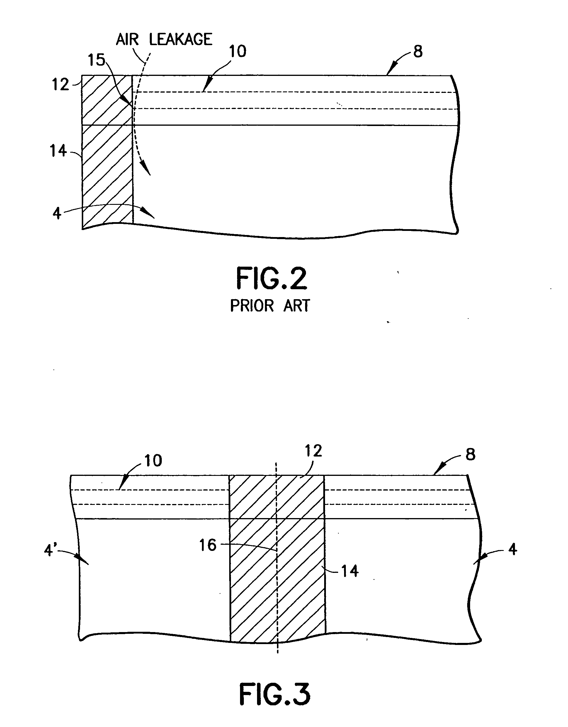
This “thermal crushing” of the plastic zipper creates a transition between “as is” zipper and crushed zipper that is susceptible to the presence of leaks through which air can enter an evacuated bag.
Another known problem afflicting evacuable storage containers is that consumers can inadvertently open an evacuable storage container too wide, so that the open zippered “mouth” of the bag is subjected to much stress where the zipper strips meet and are joined together.
If the storage container is opened too wide (over-opened), the zipper joint (where the zipper strips come together) can be stressed and damaged, leading to leaks when the bag is later closed and evacuated.

Method used


Image

  • Leakproof zipper end crush for reclosable bag and related method of manufacture
  • Leakproof zipper end crush for reclosable bag and related method of manufacture
  • Leakproof zipper end crush for reclosable bag and related method of manufacture

Examples


Embodiment Construction

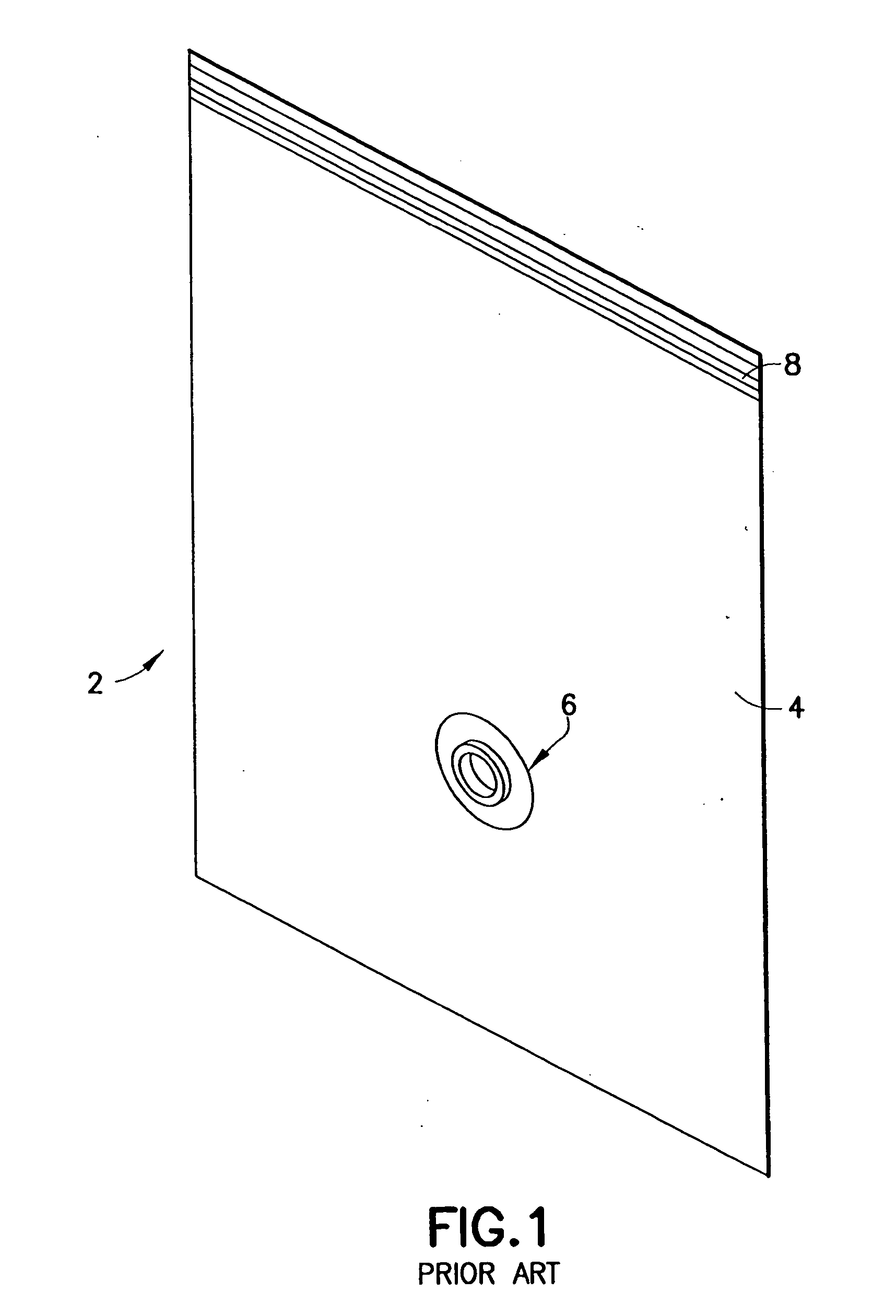
[0024]FIG. 1 shows a conventional collapsible, evacuable storage container 2 comprising a bag 4, a valve assembly 6, and a zipper 8 comprising a pair of mutually interlockable extruded zipper strips that are joined to each other at opposing ends thereof. Although not shown in FIG. 1, the conventional valve assembly 6 also typically comprises a cap that can be snapped onto a portion of the valve assembly that is disposed on the exterior of the bag 4. The cap must be removed before the bag can be evacuated, and then is replaced after the bag has been evacuated. The cap is intended to seal the valve assembly to prevent air from entering the evacuated bag.

[0025] The bag 4 typically comprises front and rear walls or panels (made of thermoplastic film material) that are joined together at the bottom and two sides by conduction heat sealing to form a receptacle having an interior volume and a mouth in which the zipper 8 is installed. One wall of bag 4 has a hole (not shown in FIG. 1) in w...


PUM

PropertyMeasurementUnit
volumeaaaaaaaaaa
pressureaaaaaaaaaa
ultrasonic wave energyaaaaaaaaaa

Abstract

A reclosable bag that can be hermetically sealed. The bag comprises a pair of zipper strips that are joined in respective zones without substantial deformation of the longitudinal profiled closure elements. These zones of zipper strip joinder assist in providing a leakproof transition from the openable section of the zipper to the corner seals, where the longitudinal profiled closure elements are either substantially deformed (e.g., crushed) or absent. The method of manufacture involves the steps of ultrasonically welding a wide area and then thermally crushing a narrower area overlapping the wide welded area to form leakproof zipper joints. This method can be applied to string (flangeless) zippers as well as flanged zippers.

Description

BACKGROUND OF THE INVENTION [0001] This invention generally relates to reclosable bags whose interior volume is hermetically sealed when the bag is closed. In particular, the invention relates to, but is not limited to, evacuable reclosable storage containers or other evacuable reclosable containers. [0002] Collapsible, evacuable storage containers typically include a flexible, airtight bag, an opening through which an article is inserted inside the bag, a zipper for closing the opening and hermetically sealing the bag, and a fixture through which excess air is evacuated from the bag. A user places an article into the bag through the opening, seals the opening, and then evacuates the air in the bag through the fixture. With the bag thus evacuated, a compressible article contained therein may be significantly compressed so that it is easier to transport and requires substantially less storage space. [0003] Collapsible, evacuable storage containers are beneficial for reasons in additi...

Claims


Application Information

Patent Timeline
Patent Type & Authority Applications(United States)
IPC IPC(8): B65D33/16B31B1/84
CPCA44B19/36Y10T156/1084B29C65/08B29C65/18B29C66/1122B29C66/3452B29C66/348B29C66/43B29C66/80B29C2793/009B29K2023/06B29K2023/065B29K2023/086B29K2023/12B29K2025/00B29K2055/02B29K2059/00B29K2067/006B29K2069/00B29K2077/00B29K2101/12B29K2995/0067B29L2005/00B29L2009/00B29L2031/7128B31B19/90B31B2219/9016B65D33/2508B65D33/2541B65D33/2591B65D81/2038A44B19/60B29C66/81431B29C66/474B29C66/47421B29C65/00B29C66/73921B29C66/71B31B70/8131B29C66/72341B29C66/72343B29K2067/00B29K2061/00B29K2027/06B29K2025/06
Inventor SHARE, LAWRENCEMATTHEWS, DAVID J.CREVIER, DONALD L.
Owner ILLINOIS TOOL WORKS INC
Learn More