Method and apparatus for transmitting a signal using simultaneous FM and AM modulation

a modulation and signal technology, applied in the field of signal transmission, can solve the problems of complex methods, special coding, and the increase of the dispersion penalty of this duobinary technique with increasing distance, and achieve the effect of widening the flat top region

Inactive Publication Date: 2006-02-09
AZNA +1
View PDF1 Cites 87 Cited by
  • Summary
  • Abstract
  • Description
  • Claims
  • Application Information

AI Technical Summary

Benefits of technology

[0041] the amplitude profile of the 1 bit is substantially bell-shaped, and the frequency profile of

Problems solved by technology

However, this method is also complex and requires special coding.
Additionally, in cases where the digital signal must p

Method used


Image

  • Method and apparatus for transmitting a signal using simultaneous FM and AM modulation
  • Method and apparatus for transmitting a signal using simultaneous FM and AM modulation
  • Method and apparatus for transmitting a signal using simultaneous FM and AM modulation

Examples


Embodiment Construction

Phase Coding by Direct Modulation

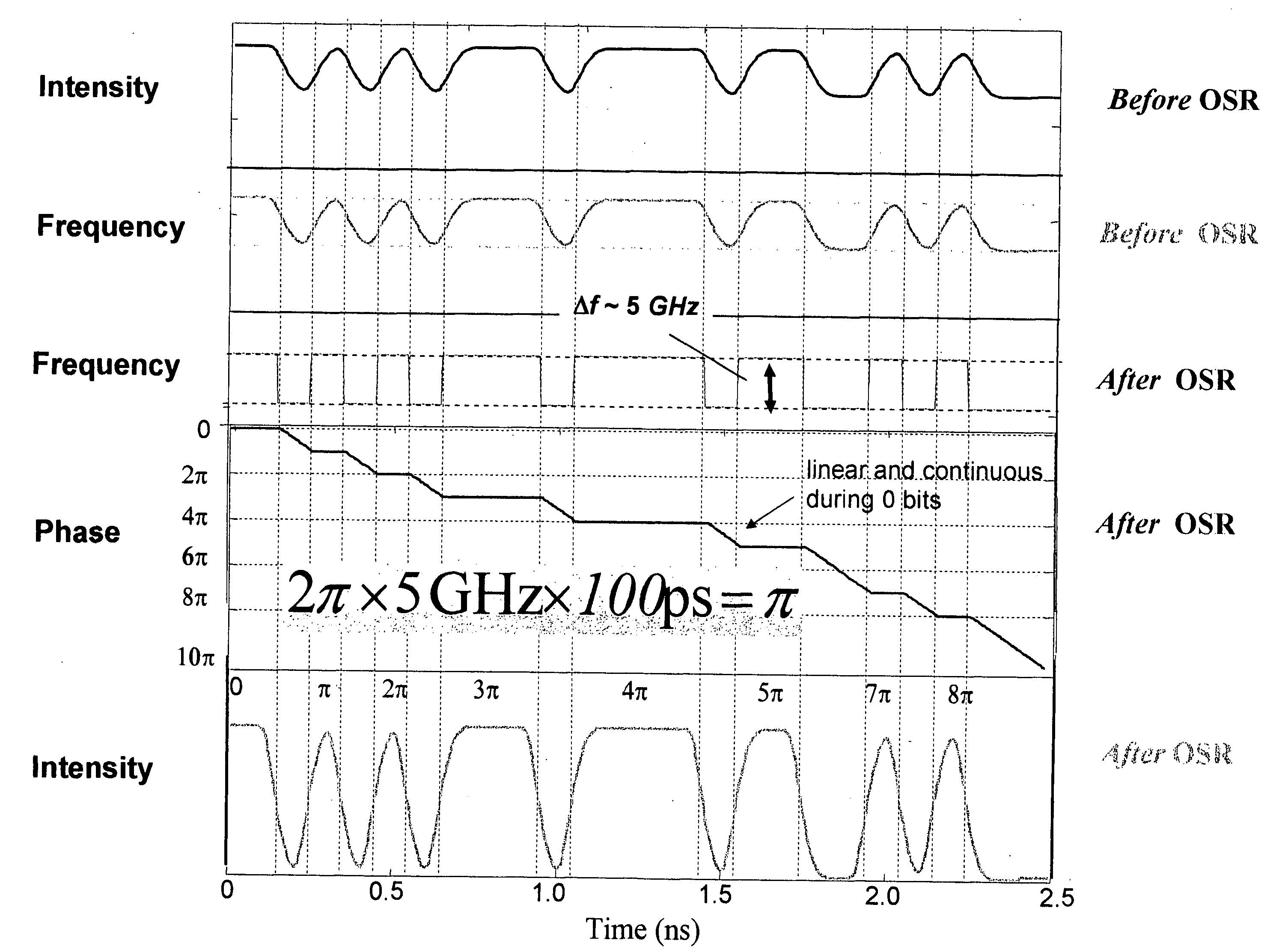
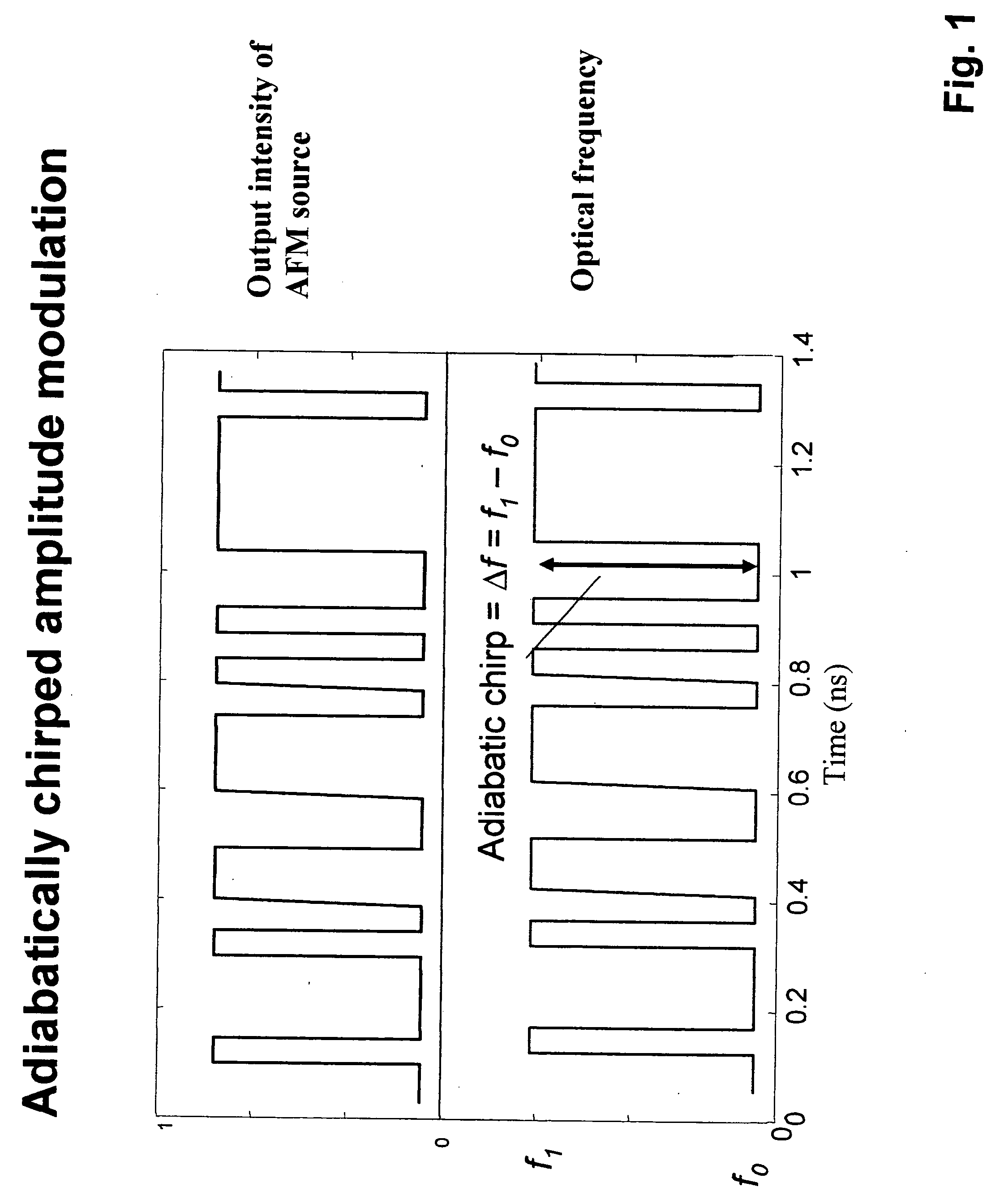
[0051] In one preferred embodiment of the present invention, a frequency modulated source, such as a directly modulated Distributed Feedback (DFB) laser, is modulated with a digital signal. The laser is biased high above threshold, for example at 80 mA, and modulated with a small current modulation to provide a signal with a small Extinction Ratio (ER) of ˜1-3 dB. Because of the linewidth enhancement effect and gain compression in the laser, the optical frequency of the laser has approximately the same temporal profile as the intensity modulation, as shown in FIG. 1. This property of directly modulated lasers has been known to those skilled in the art.

[0052] The instantaneous frequency of the laser changes between two extremes (f1 and f0), and this difference (Δf) is sometimes referred to herein as adiabatic chirp. The Extinction Ratio (ER) of the output (defined as the ratio of the 1 bit mean amplitude to the 0 bit mean amplitude) can be varied ov...


PUM


Abstract

There is provided method for transmitting binary data contained in respective successive time cells, the data being in the form of an optical signal obtained by amplitude modulation and frequency modulation of an optical carrier wave, with a 0 bit data value having a 0 bit mean amplitude having a 0 bit amplitude time duration and a 0 bit frequency having a 0 bit frequency duration, and a 1 bit data value having a 1 bit mean amplitude having a 1 bit amplitude time duration and a 1 bit frequency having a 1 bit frequency duration; the improvement wherein: independently adjusting the 0 bit mean amplitude relative to the 1 bit mean amplitude; independently adjusting the 0 bit frequency relative to the 1 bit frequency; and independently adjusting time duration of the frequency profile of the 1 bit relative to the time duration of the amplitude profile of the 1 bit, whereby to extend the error-free propagation of the optical signal though a dispersive optical fiber beyond the dispersion limit. There is provided a method for transmitting Non-Return-To-Zero (NRZ) binary data contained in respective successive time cells, the data being in the form of an optical signal obtained by amplitude modulation and frequency modulation of an optical carrier wave, with a 0 bit data value having a 0 bit mean amplitude having a 0 bit amplitude time duration and a 0 bit frequency having a 0 bit frequency duration, and a 1 bit data value having a 1 bit mean amplitude having a 1 bit amplitude time duration and a 1 bit frequency having a 1 bit frequency duration; the improvement wherein: the phase across each 1 bit data value is substantially constant, and the phase of the carrier changes across each and every 0 bit by an amount equal to the product of the frequency difference between the 1 bit and the 0 bit and the duration of the 0 bit; whereby to extend the error-free propagation of the optical signal though a dispersive optical fiber beyond the dispersion limit. In accordance with one form of the present invention, there is provided a method for transmitting binary data contained in respective successive time cells, the data being in the form of an optical signal obtained by amplitude modulation and frequency modulation of an optical carrier wave, with a 0 bit data value having a 0 bit mean amplitude having a 0 bit amplitude time duration and a 0 bit frequency having a 0 bit frequency duration, and a 1 bit data value having a 1 bit mean amplitude having a 1 bit amplitude time duration and a 1 bit frequency having a 1 bit frequency duration; the improvement wherein: the amplitude profile of the 1 bit is substantially bell-shaped, and the frequency profile of the 1 bit is substantially square-shaped, with steeper rise and fall time and a wider flat top region; whereby to extend the error-free propagation of the optical signal though a dispersive optical fiber beyond the dispersion limit.

Description

REFERENCE TO PENDING PRIOR PATENT APPLICATIONS [0001] This patent application: [0002] (i) claims benefit of pending prior U.S. Provisional Patent Application Ser. No. 60 / 554,249, filed Mar. 18, 1004 by Daniel Mahgerefteh et al. for METHOD AND TRANSMISSION USING PARTIAL FM AND AM MODULATION (Attorney Docket No. TAYE-33 PROV); [0003] (ii) claims benefit of pending prior U.S. Provisional Patent Application Ser. No. 60 / 554,243, filed Mar. 18, 2004 by Daniel Mahgerefteh et al. for FLAT CHIRP INDUCED BY FILTER EDGE (Attorney Docket No. TAYE-34 PROV); [0004] (iii) claims benefit of pending prior U.S. Provisional Patent Application Ser. No. 60 / 569,769, filed May 10, 2004 by Daniel Mahgerefteh et al. for FLAT CHIRP INDUCED BY AN OPTICAL FILTER EDGE (Attorney Docket No. TAYE-40 PROV); [0005] (iv) claims benefit of pending prior U.S. Provisional Patent Application Ser. No. 60 / 569,768, filed May 10, 2004 by Daniel Mahgerefteh et al. for METHOD OF TRANSMISSION USING PARTIAL FM AND AM MODULATION ...

Claims


Application Information

Patent Timeline
IPC IPC(8): H04B10/04
CPCH04B10/508
Inventor MAHGEREFTEH, DANIELMATSUI, YASUHIROTAYEBATI, PARVIZZHENG, XUEYAN
Owner AZNA
Why Eureka
Try Eureka