Plunger pump and method of controlling discharge of the pump

a technology of pump and discharge amount, which is applied in the direction of pump, positive displacement liquid engine, piston pump, etc., can solve the problems of large number of components, complicated valve structure, and complicated assembly, so as to reduce both noise and vibration in using the pump, and easily change the amount of discharge. , the effect of reducing the number of components

Inactive Publication Date: 2006-02-09
MIKUNI CORP
View PDF20 Cites 5 Cited by
  • Summary
  • Abstract
  • Description
  • Claims
  • Application Information

AI Technical Summary

Benefits of technology

[0041] Thus, according to the plunger pump and method of controlling discharge of the pump of the invention, a desired compression rate is obtained, and it is possible to change a discharge amount with ease without changing a stroke of the plunger and/or the inner diameter of a sliding hole of the plunger, and to discharge a c

Problems solved by technology

In the conventional pump structure as shown in FIG. 8, two-component valves (suction valve 125 and discharge valve 130) each comprised of the sphere-shaped valve body and spring are provided on both the suction side S and discharge side D. There arise problems that the number of components is large, the valve structure is complicated, the assembly is also complicated, and that the entire plunger pump is upsized.
Therefore, the compression rate decreases, and substantially adverse effects are exerted in increases in discharge pressure and in air exclusion.
Moreover, in the conventional pump structure as shown in FIG. 8, changing a discharge flow amount requires changes in stroke of the pl

Method used


Image

  • Plunger pump and method of controlling discharge of the pump
  • Plunger pump and method of controlling discharge of the pump
  • Plunger pump and method of controlling discharge of the pump

Examples


Embodiment Construction

[0057] Embodiments of the present invention will specifically be described below with reference to accompanying drawings.

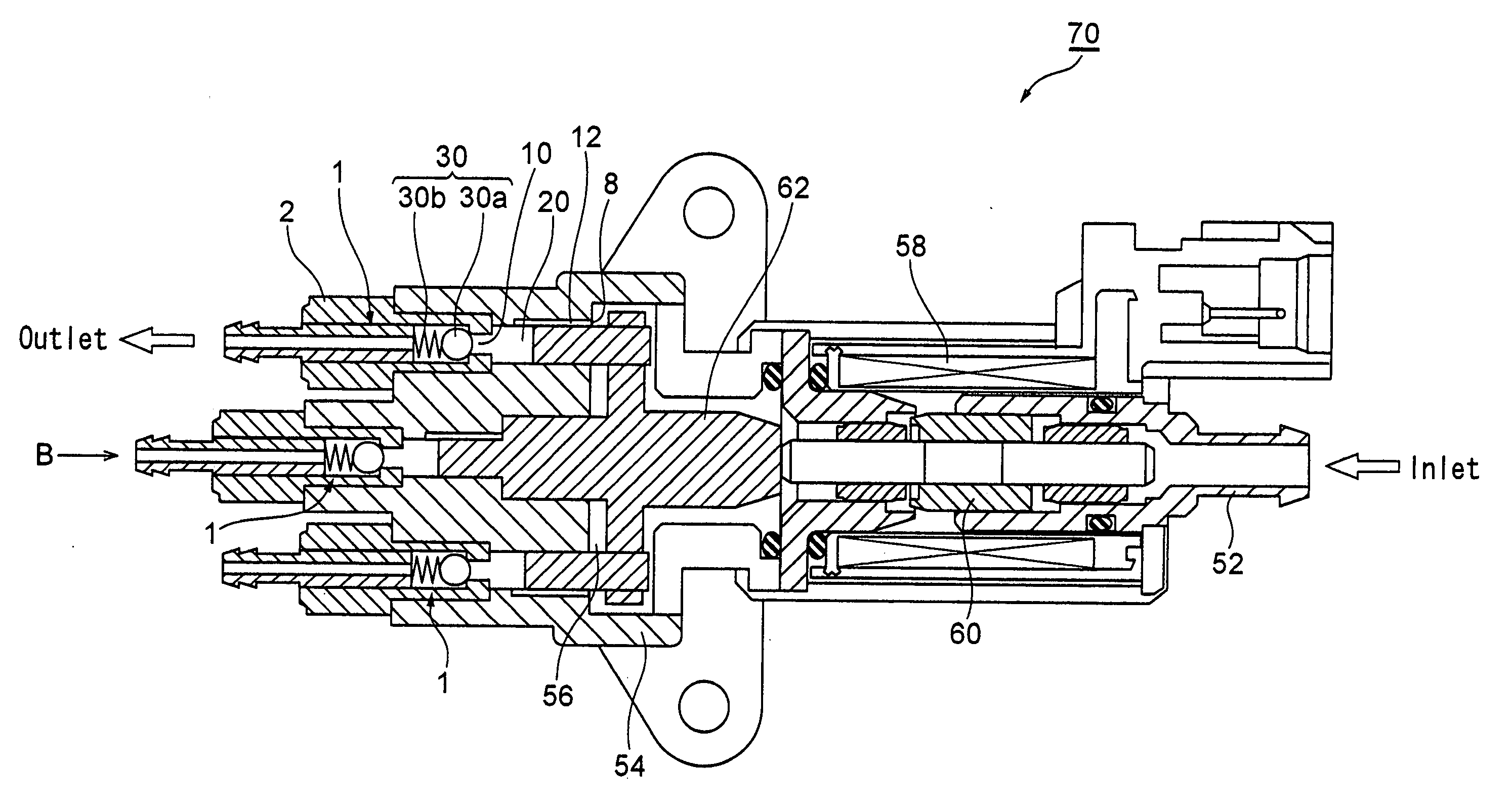
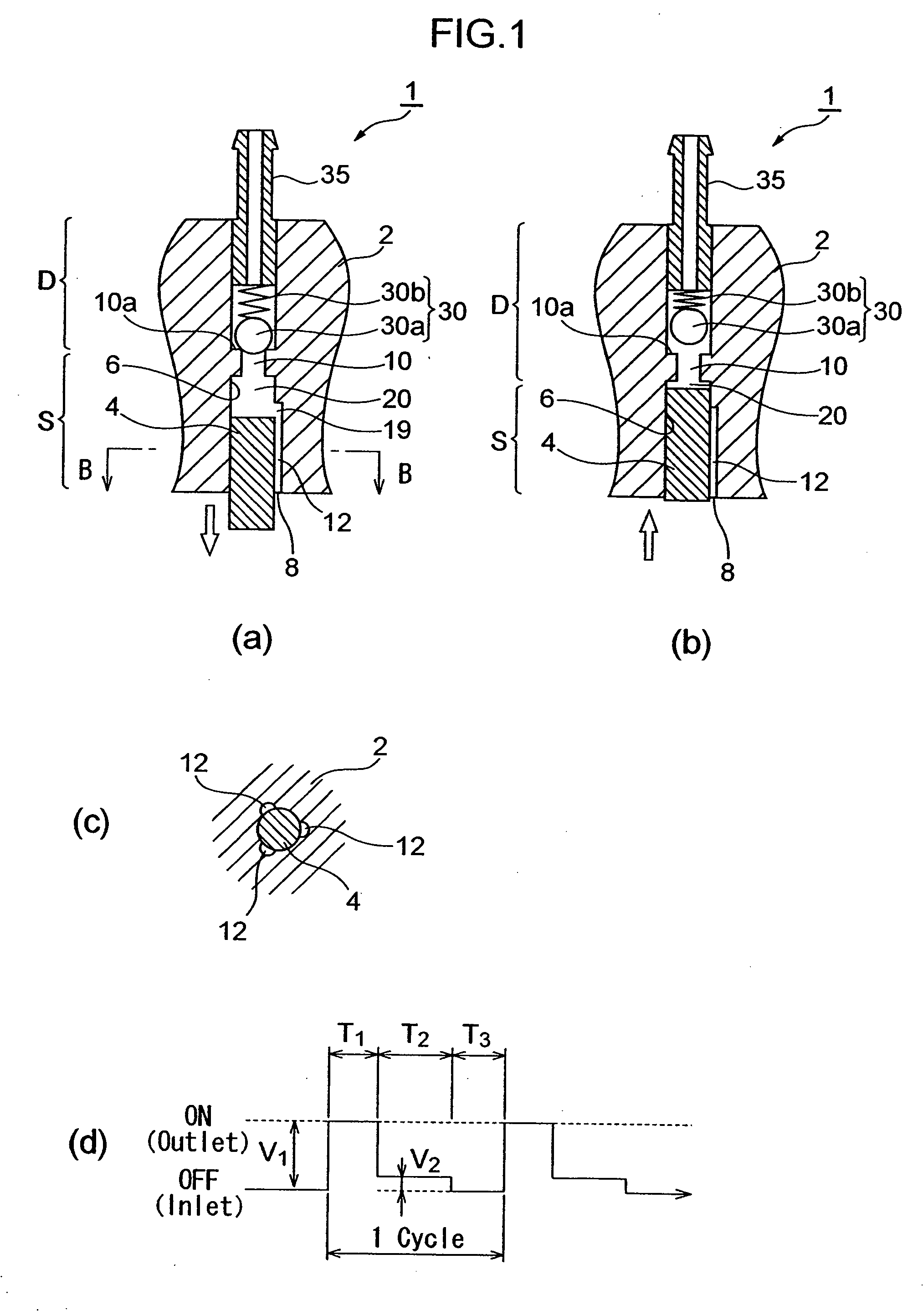
[0058]FIG. 1 shows a plunger pump 1 according to one embodiment of the invention. As shown in the figure, the plunger pump 1 of this embodiment is provided with a cylinder 2, and a cylindrical plunger 4 inserted in the cylinder 2 slidably. More specifically, the cylinder 2 has a suction side S and discharge side D, and the plunger 4 is inserted slidably in a circular cross-section continuous hole 6 formed on the suction side S of the cylinder 2. The plunger 4 is provided with an inlet 8 to suck a fluid such as lubricant oil from a fluid source such as a reservoir tank not shown. The cylinder 2 is provided with an outlet 10 that discharges the fluid sucked through the inlet 8 and that is communicated with the continuous hole 6.

[0059] The plunger 4 is slid inside the continuous hole 6 by the electromagnetic activation force generated by applying current to an elec...


PUM


Abstract

There are provided a plunger pump and method of controlling discharge of the pump capable of obtaining a desired compression rate, changing a discharge amount with ease without changing a stroke of the plunger and/or the inner diameter of a sliding hole of the plunger, and discharging a constant amount of fluid with accuracy while preventing the fluid from leaking. A plunger pump 1 has a cylinder 2 having an inlet 8 to suck a fluid and an outlet 10 to discharge the sucked fluid, a continuous hole 6 which is formed inside the cylinder 2 and communicated with the outlet 10, a plunger 4 which is inserted in the continuous hole 6 to be slidable and forms a pump chamber 20 to suck and discharge the fluid with the outlet 10 where the pump chamber 20 is formed between the plunger 4 and the outlet 10, and a fluid suction passage which is formed in the cylinder or the plunger, to suck a fluid into the pump chamber, wherein an opening 19 of the fluid suction passage 12 opened to the pump chamber 20 is opened and closed by the plunger 4 sliding inside the continuous hole 6.

Description

BACKGROUND OF THE INVENTION [0001] 1. Field of the Invention [0002] The present invention relates to a plunger pump that sucks a constant amount of fluid from a fluid source to discharge and to a method of controlling discharge of the pump. [0003] 2. Description of Related Art [0004] In plunger pumps that suck and discharge a fluid by reciprocating motion of a plunger, various manners have conventionally been proposed for the driving form of the plunger, arrangement form of valves and the like. For example, Patent Documents 1 to 3 each disclose a plunger type electromagnetic pump that reciprocates a plunger with electromagnetic activation force generated by applying current to an electromagnetic coil. [0005]FIG. 8 illustrates a plunger type electromagnetic pump of the same type as that of the electromagnetic pump disclosed in Patent Documents 1 to 3. As shown in the figure, a plunger pump 100 has a cylinder 102, and a plunger 104 that is inserted in the cylinder 102 to be slidable. ...

Claims


Application Information

Patent Timeline
IPC IPC(8): A61M1/00F04B41/06
CPCF04B7/04F04B23/06F04B17/042
Inventor TAKEHANA, NORIOKUSANAGI, HIDEAKI
Owner MIKUNI CORP
Why Eureka
Try Eureka