Unlock instant, AI-driven research and patent intelligence for your innovation.

Transceiver and receiver

a technology of receiver and receiver, which is applied in the field of transmitter/receiver and receiver, can solve the problems of insufficient reception condition of received wave, difficult to precisely detect, and likely deterioration of receive characteristic, and achieve the effect of high degree of accuracy

Inactive Publication Date: 2006-02-09
MITSUBISHI ELECTRIC CORP
View PDF13 Cites 11 Cited by
  • Summary
  • Abstract
  • Description
  • Claims
  • Application Information

AI Technical Summary

Benefits of technology

The present invention provides a transmitter / receiver with a receiving section that can control power supply to a receiving section with high accuracy. The transmitter / receiver includes a controller and a memory that stores values of power supply to the receiving section based on the transmission power and the quality of service of the received wave. The controller makes reference to the stored values to control power to the receiving section during transmission. The transmitter / receiver can detect the power of the transmission wave and the quality of service of the received wave, and the controller adjusts power to the receiving section accordingly. This allows for precise control of power supply to the receiving section based on the strength of the transmission wave and the quality of service. The invention also provides a method for detecting the power of the transmission wave and adjusting power to the receiving section accordingly.

Problems solved by technology

In a device such as a mobile phone implementing a W-CDMA (wideband code division multiple access) system in which transmission and receipt temporally coincide, however, a transmission wave has an effect on a received wave, whereby deterioration of the receive characteristic is likely.
The reception condition of the received wave is thus insufficient to provide a high degree of accuracy in controlling the power supply to the receiving section.
This causes difficulty in precisely detecting the reception condition from the initial stage of one intermittent reception to control the power supply to the receiving section with a high degree of accuracy.

Method used


Image

  • Transceiver and receiver
  • Transceiver and receiver
  • Transceiver and receiver

Examples


first embodiment

[0042] A first embodiment is directed to a transmitter / receiver for controlling the power supply to a receiving section on the basis of transmission power of a transmission wave (which may be alternatively referred to as transmission wave power) as well as quality of service of a received wave.

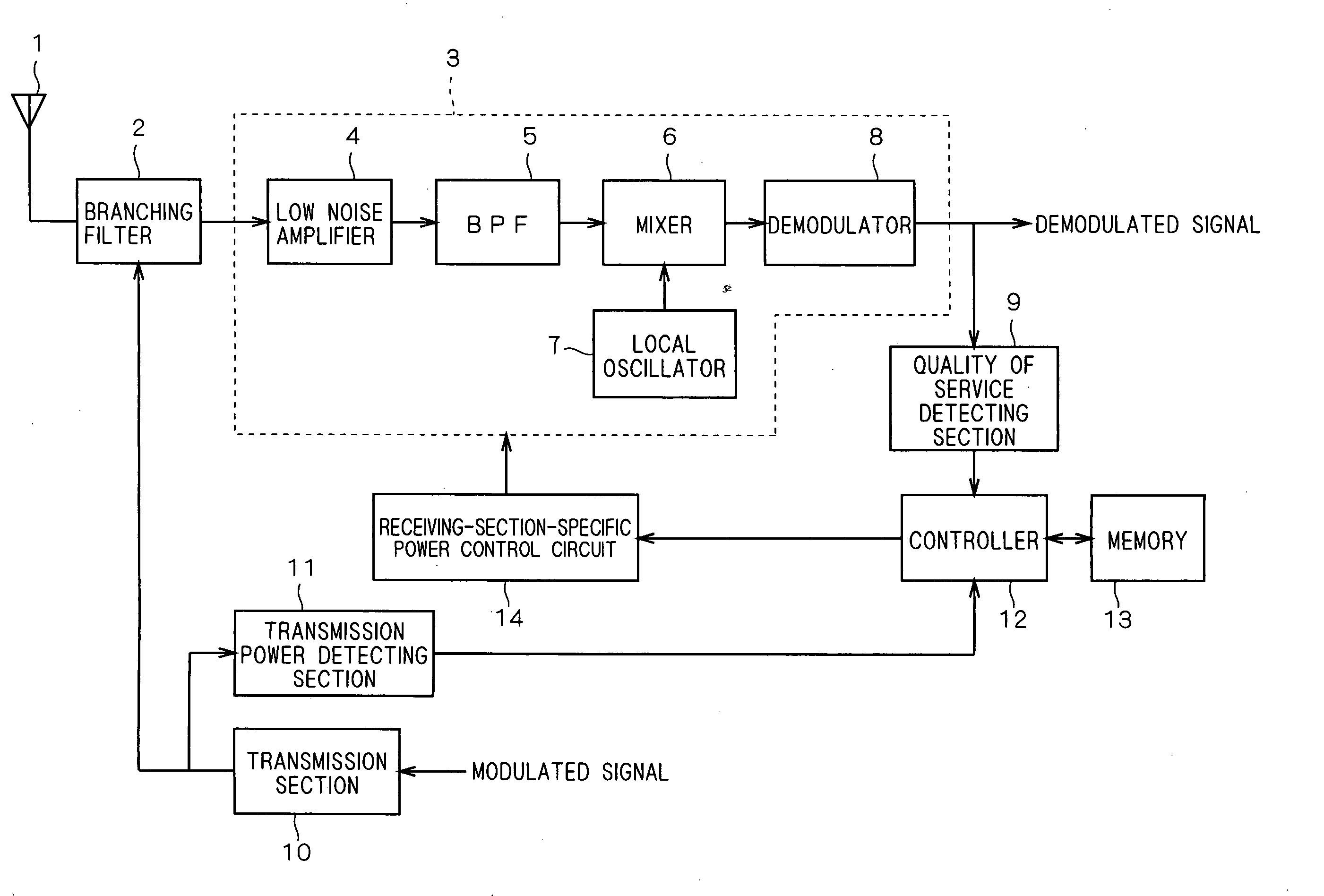
[0043]FIG. 1 shows the configuration of a transmitter / receiver according to the present embodiment. A received wave from a base station (not shown) is received at an antenna 1, and is then sent through a branching filter 2 to a receiving section 3.

[0044] The receiving section 3 includes an LNA (low noise amplifier) 4, a BPF (band pass filter) 5, a mixer 6, a local oscillator 7, and a demodulator 8. The low noise amplifier 4 amplifies the received wave, and the received wave thus amplified is subjected to filtering at the BPF 5 to produce a signal of a predetermined frequency band. The received wave as filtered is subjected to frequency conversion at the mixer 6 which receives a signal of a p...

second embodiment

[0060] A second embodiment is directed to a receiver implementing intermittent reception. Based on the average of the quality of service in intermittent reception in the past, the receiver controls the power supply to a receiving section.

[0061]FIG. 5 shows the configuration of the receiver according to the present embodiment which includes the antenna 1, branching filter 2, receiving section 3, quality of service detecting section 9, controller 12, memory 13, and the receiving-section-specific power control circuit 14 that are the same in configuration as those of the transmitter / receiver of the first embodiment. The receiving section 3 is allowed to perform intermittent reception. The present embodiment is directed to a receiver and thus does not include the transmission power detecting section 11 and transmission section 10. Alternatively, the present embodiment may include these sections to constitute a transmitter / receiver.

[0062] The receiver of the present embodiment further ...

third embodiment

[0083] A third embodiment is a modification of the transmitter / receiver according to the first embodiment. The controller 12 receives a transmission power control signal instead of the detection result obtained in the transmission power detecting section 11, to obtain the information about the transmission power of a transmission wave during transmission.

[0084]FIG. 8 shows the configuration of a transmitter / receiver according to the present embodiment. The transmitter / receiver of the present embodiment includes the antenna 1, branching filter 2, receiving section 3, quality of service detecting section 9, transmission section 10, controller 12, memory 13 and receiving-section-specific power control circuit 14 which also constitute the transmitter / receiver of the first embodiment.

[0085] In the transmitter / receiver, a demodulated signal demodulated in the demodulator 8 (which is namely a baseband signal) is generally subjected to signal processing. In FIG. 8, a baseband section resp...


PUM


Abstract

A transmitter / receiver and a receiver such as a mobile phone or a transceiver capable of controlling power supply to a receiving section with a high degree of accuracy. The transmitter / receiver may include: a receiving section; a quality of service detecting section; a transmission section for generating a transmission wave; a transmission power detecting section for detecting power of the transmission wave; a controller; and a memory, for example. The memory stores values of power supply that are responsive to the quality of service of the received wave and the transmission power of the transmission wave. The controller makes reference to the values of power supply stored in the memory to control the power to be supplied to the receiving section based on the detection result at the quality of service detecting section and the detection result at the transmission power detecting section.

Description

TECHNICAL FIELD [0001] The present invention relates to a transmitter / receiver and a receiver such as a mobile phone or a transceiver, and more particularly, to a transmitter / receiver and a receiver effectively usable for reduction in power consumption. BACKGROUND ART [0002] A transmitter / receiver and a receiver such as a mobile phone has a section for receiving a high-frequency radio signal. The greater power supplied to the receiving section generally allows the transmitter / receiver and receiver to operate at the maximum operating point of the receiving section. As a result, improved NF (noise figure), distortion characteristics and receive gain of a received wave are obtained, which results in improved receive characteristic. Conversely, the smaller power supplied to the receiving section causes deviation from the maximum operating point to result in reduction in receive characteristic, which in turn allows reduced power consumption. The power to be supplied to the receiving sect...

Claims


Application Information

Patent Timeline
Patent Type & Authority Applications(United States)
IPC IPC(8): H04B7/00H04B1/00H04Q7/20H04W52/02H04W52/26
CPCH04W52/265H04W52/0251Y02D30/70
Inventor NAKAMIZO, HIDEYUKIITO, TATSUYA
Owner MITSUBISHI ELECTRIC CORP