Vehicle motion control device and method

a technology of motion control device and vehicle, which is applied in the direction of cycle equipment, instruments, tractors, etc., can solve the problems of steering stability degradation, loss of stability against disturbance, and insufficient consideration of stability and response, so as to achieve superior stability and response, and effectively utilize the effect of tire grip

Inactive Publication Date: 2006-02-09
SUBARU CORP
View PDF3 Cites 30 Cited by
  • Summary
  • Abstract
  • Description
  • Claims
  • Application Information

AI Technical Summary

Benefits of technology

[0011] In view of the above circumstances, the objective of the present invention is to provide a vehicle motion control device capable of controlling the driving force distribution to the wheels with superior stability and response while effectively utilizing the tire grip.

Problems solved by technology

However, the main focus of the technologies described above is the effective utilization of the driving force; thus, issues such as stability and response are not fully considered.
In particular, if the wheel friction utilization ratio is controlled to the limit during spinning, the control mechanism would rely heavily on the grip of the tires on the outer wheels, leading to problems such as the loss of stability against disturbances due to, for example, a sudden change in the friction coefficient with the road surface.
In other words, in the technologies described above, the nonlinear elements of the vehicle motion are not properly taken into consideration in controlling the vehicle behavior; as a result, there is a possibility that steering stability gets degraded.

Method used


Image

  • Vehicle motion control device and method
  • Vehicle motion control device and method
  • Vehicle motion control device and method

Examples


first embodiment

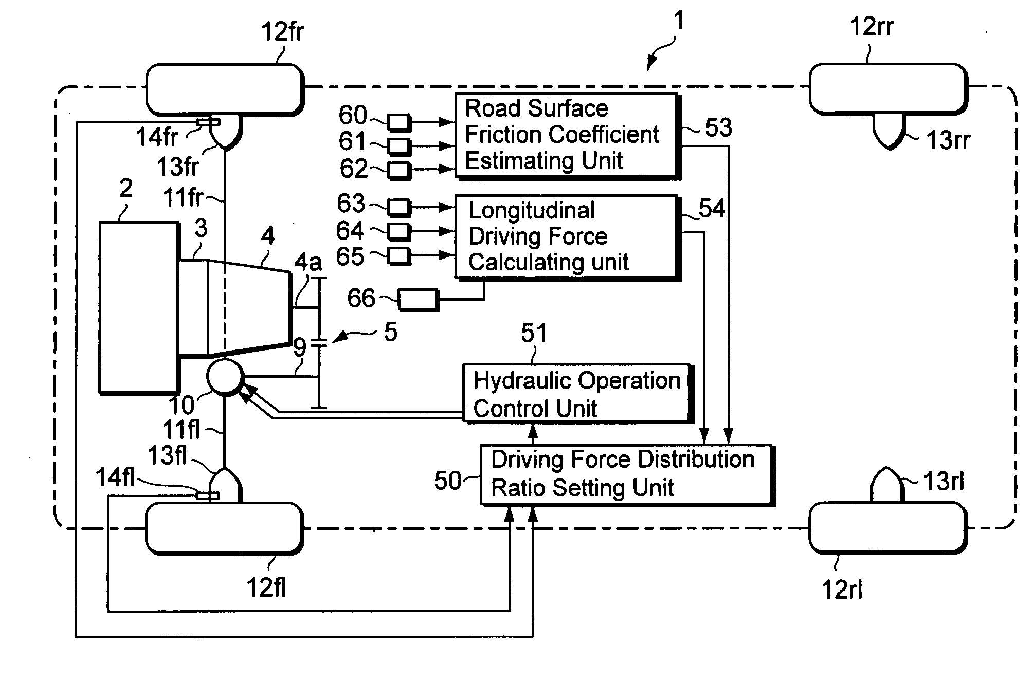
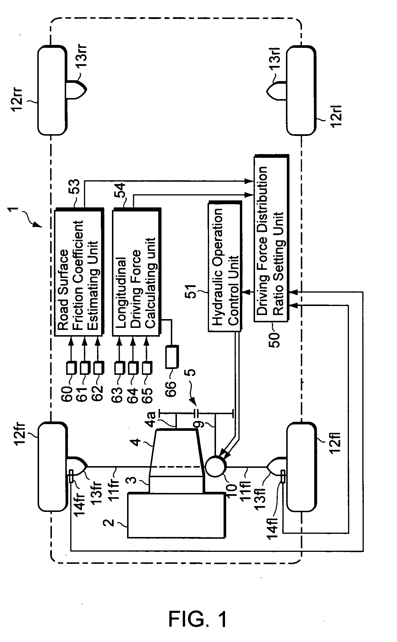
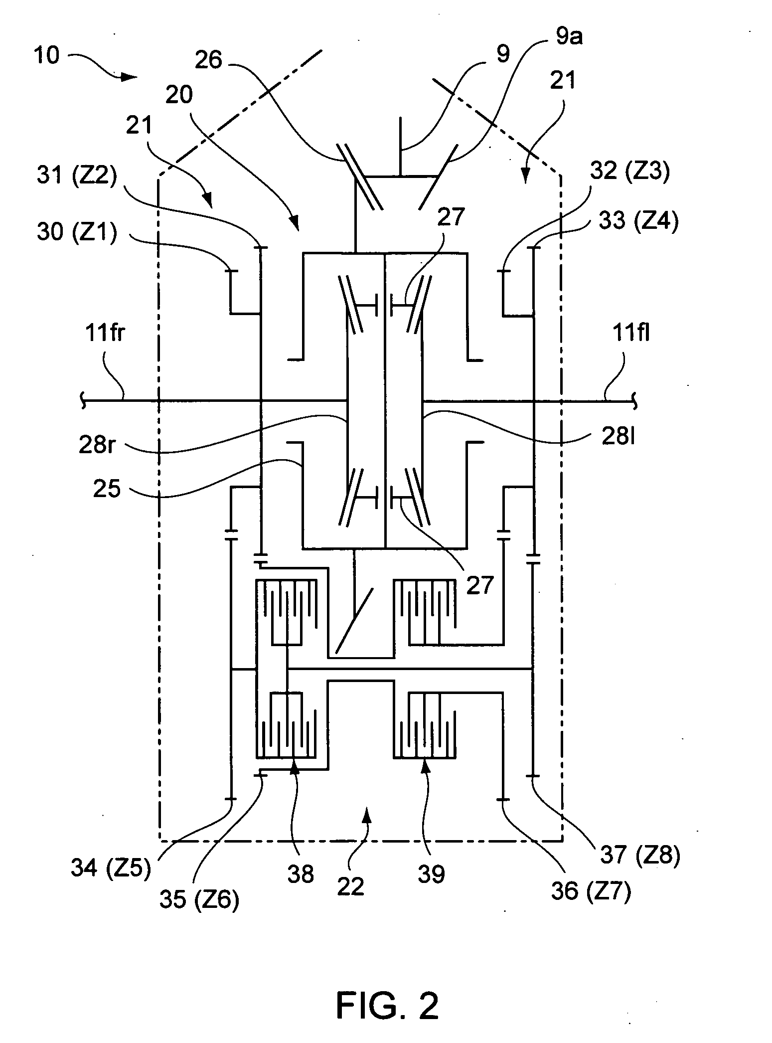
[0037] A first example of a first embodiment according to the present invention is described below with reference to the accompanying drawings. FIG. 1 is a schematic diagram of a driving force distribution control device, FIG. 2 is a skeleton diagram showing the schematic structure of a front wheel final velocity reduction device, FIG. 3 is an explanatory diagram showing an equivalent two-wheel vehicle model for a 4-wheel vehicle, and FIG. 4 is an explanatory diagram showing the equations of motion functionally based on the vehicle motion model.

[0038] In FIG. 1, the reference numeral 1 indicates a vehicle such as an automobile. In the present embodiment, the vehicle 1 is a front wheel drive automobile, where a driving force generated by an engine 2 is transmitted through a torque converter 3 and a transmission 4 to a transmission output axle 4a. The driving force transmitted to the transmission output axle 4a is further transmitted through a reduction gear array 5 to a drive axle (...

second embodiment

[0083] Prior to describing the system structure and system processes regarding the vehicle motion control device according to a second embodiment, first the system matrix in the equations of state is explained below in order to define the control concept. Note that the braking force can be viewed as the reverse-direction component (the negative component) of the driving force, and thus the “driving force” in the present embodiment is defined to include the braking force.

[0084]FIG. 7 is an explanatory diagram of a vehicle model. The vehicle model shown in this figure is a two-wheel model to represent the state of motion of the vehicle in terms of a front wheel and a rear wheel. In this vehicle model, the state of motion of the vehicle is expressed in terms of the rotational motion (the yaw motion) around the vertical axis (the Z axis), and the translational motion in the lateral direction (the Y axis). When the front wheel is steered (and the rear wheel is parallel to the X axis), t...

third embodiment

[0116] In the second embodiment, the values of the nonlinear term were calculated while varying the driving force distribution ratio r from 0.00 to 1.00 in a stepwise manner in Eq. (44) to thereby determine the target value r* which is the driving force distribution ratio r that yields the smallest of the calculated nonlinear term values. However, in Eq. (44) there are some cases wherein the value in the square root becomes negative, so that it is not possible to obtain the driving force distribution ratio r. Therefore, in actual control, it is preferable to determine the driving force distribution ratio r using the following expression: kf·Ff—⁢yμ2·Ff—⁢z2-(Ff—⁢Lim-r2·Ff—⁢div)2+kr·Fr—⁢yμ2·Fr—⁢z2-(Ff—⁢Lim-1-r2·Fr—⁢div)2⁢(45)

where Ff_Lim is a per-wheel maximum value of the driving force applied to the front wheels 76f (hereinafter termed “front wheel maximum value”), which is the product of the friction coefficient μ and the per-wheel vertical force Ff_z for the front wheels 76f; and...


PUM


Abstract

The objective of the present invention is to provide a vehicle motion control device capable of controlling the driving force distribution to the wheels with superior stability and response while effectively utilizing the tire grip. Specifically, the present invention provides a vehicle motion control device for a vehicle, the vehicle having a plurality of wheels and a driving device for driving the wheels based on a driving force/load distribution ratio, having: a force detection unit for detecting forces that act on the wheels; a target distribution ratio calculating unit for obtaining nonlinear terms by use of a group of parameters including the forces detected by the force detection unit, and obtaining a target value of the driving force/load distribution ratio so as to minimize the nonlinear terms, the nonlinear terms being included in elements of a system matrix of equations of state that describe a state of motion of the vehicle; and a driving device control unit for controlling the driving device based on the target value of the driving force/load distribution ratio.

Description

CROSS REFERENCE TO RELATED APPLICATIONS [0001] This application claims priority under 35 U.S.C. 119 based upon Japanese Patent Application Serial No. 2004-227639, filed on Aug. 3, 2004, Japanese Patent Application Serial No. 2004-228431, filed on Aug. 3, 2004, and Japanese Patent Application Serial No. 2005-065624, filed on Mar. 9, 2005. The entire disclosures of the aforesaid applications are incorporated herein by reference. BACKGROUND OF THE INVENTION [0002] 1. Field of the Invention [0003] The present invention relates to vehicle motion control devices and methods, and, in particular, to devices and methods for controlling the motion of a vehicle through controlling the distribution ratio of the driving force based on the forces that act on the wheels. [0004] 2. Description of the Related Art [0005] Conventionally, there are known technologies for controlling the state of motion of a vehicle through controlling the distribution ratio of the driving force between the front and re...

Claims


Application Information

Patent Timeline
Patent Type & Authority Applications(United States)
IPC IPC(8): G06F17/00
CPCB60K17/3462B60K23/04B60K23/0808B60W30/02B60W40/064B60W2720/403B60W2520/30B60W2530/20B60W2550/148B60W2710/105B60W2040/1307B60W2552/40
Inventor TSUKASAKI, YUICHIROKOGURE, MASARU
Owner SUBARU CORP
Why Eureka
Try Eureka