Finite element analysis tire footprint smoothing algorithm using multiple load cases

a technology of tire footprint and load case, applied in the field offinite element analysis, can solve the problems of increasing the resolution of fea mesh, processing time, processing resources (e.g. dynamic memory, processing cycles, etc.), and the processing time required, so as to improve the accuracy and resolution of simulated contact shape boundaries.

Inactive Publication Date: 2006-02-09
BRIDGESTONE FIRESTONE NORTH AMERICAN TIRE
View PDF17 Cites 21 Cited by
  • Summary
  • Abstract
  • Description
  • Claims
  • Application Information

AI Technical Summary

Benefits of technology

[0008] In accordance with the present invention, a method and apparatus for predicting the shape of a contact region of a finite element model deformed against a contact surface. The contact surface may be a rigid body or another finite element model. The shape of a contact region is dictated by the node / element distribution in response to a simulated load. The described approach uses curve fitting to predict the boundary of a contact region for a specified load condition based upon an analysis of contact region shapes generated by finite element analysis for each load within a range of simulated loads. In this manner, the discrete nature of the contact region boundary typically associated with finite element analysis results based upon a single load analysis is overcome using information derived from multiple previous load simulations. The approach improves the accuracy and resolution of simulated contact shape boundaries without a corresponding increase in processing resources.

Problems solved by technology

A commonly recognized problem associated with conventional finite element analysis (FEA) techniques is that processor resources (e.g. dynamic memory, processing cycles, non-volatile storage, etc.), as well as processing time required to perform an FEA analysis, increase in response to increases in the FEA mesh resolution.
Unfortunately, the discrete nature of finite element analysis is most pronounced at the outer edges of the finite element analysis region.
Unfortunately, FEA mesh resolutions sufficiently fine to smooth image boundaries typically result in unacceptable increases in processor resources, as described above.
Researchers attempting to use finite element analysis to study contact regions between objects in contact with one another are particularly hard-hit by the unfortunate relationship between FEA mesh resolutions and increases in processor resources, described above.
An inability of conventional finite element analysis techniques to provide timely and accurate contact region boundary information significantly reduces the value of finite element analysis to researchers in this field of study.

Method used


Image

  • Finite element analysis tire footprint smoothing algorithm using multiple load cases
  • Finite element analysis tire footprint smoothing algorithm using multiple load cases
  • Finite element analysis tire footprint smoothing algorithm using multiple load cases

Examples


Embodiment Construction

[0023] Exemplary embodiments according to the present invention are described below with reference to the above drawings, in which like reference numerals designate like components.

[0024] Exemplary embodiments of the present invention relate to a novel method and apparatus for predicting the shape of a contact region of a finite element model deformed against a contact surface.

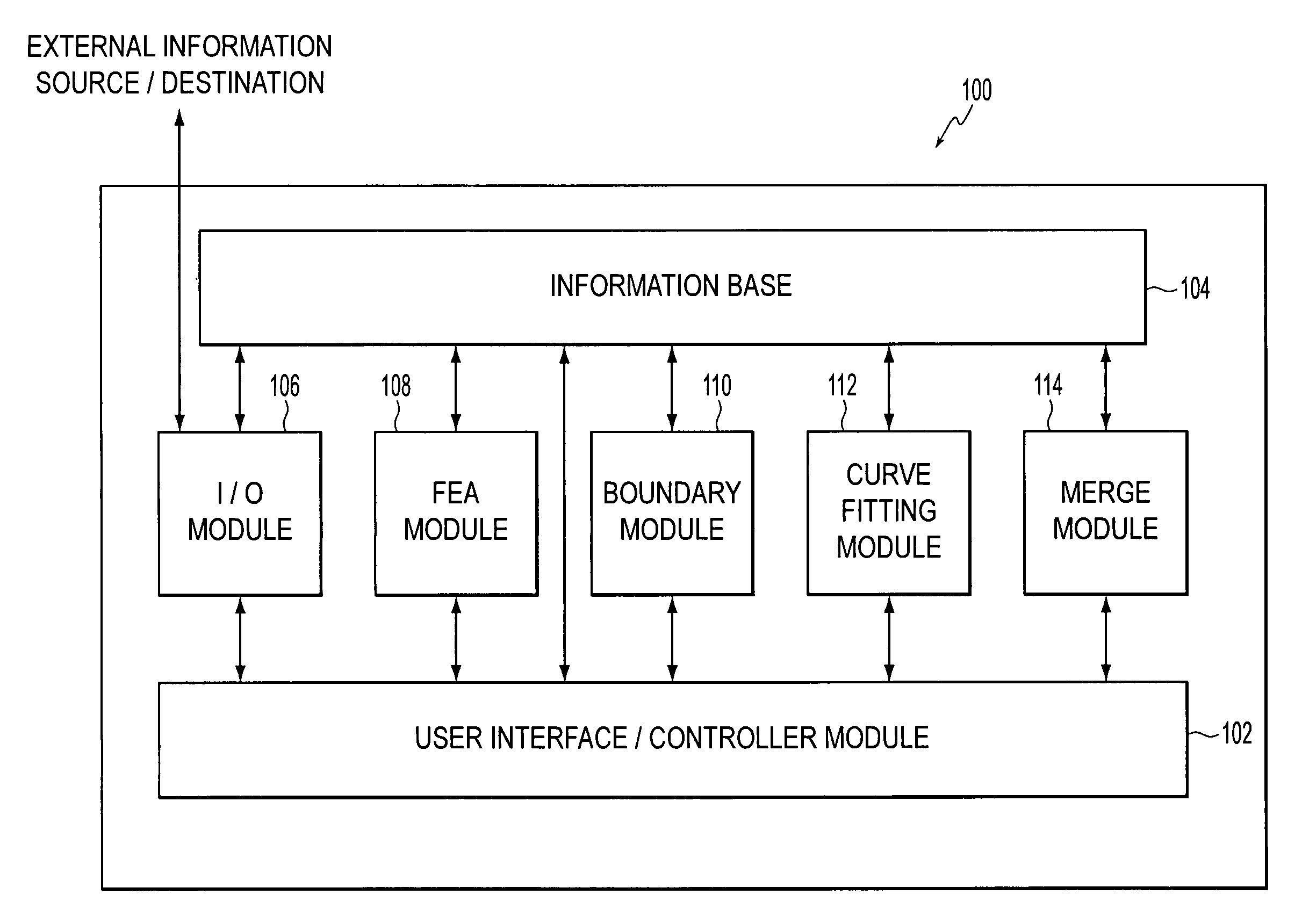
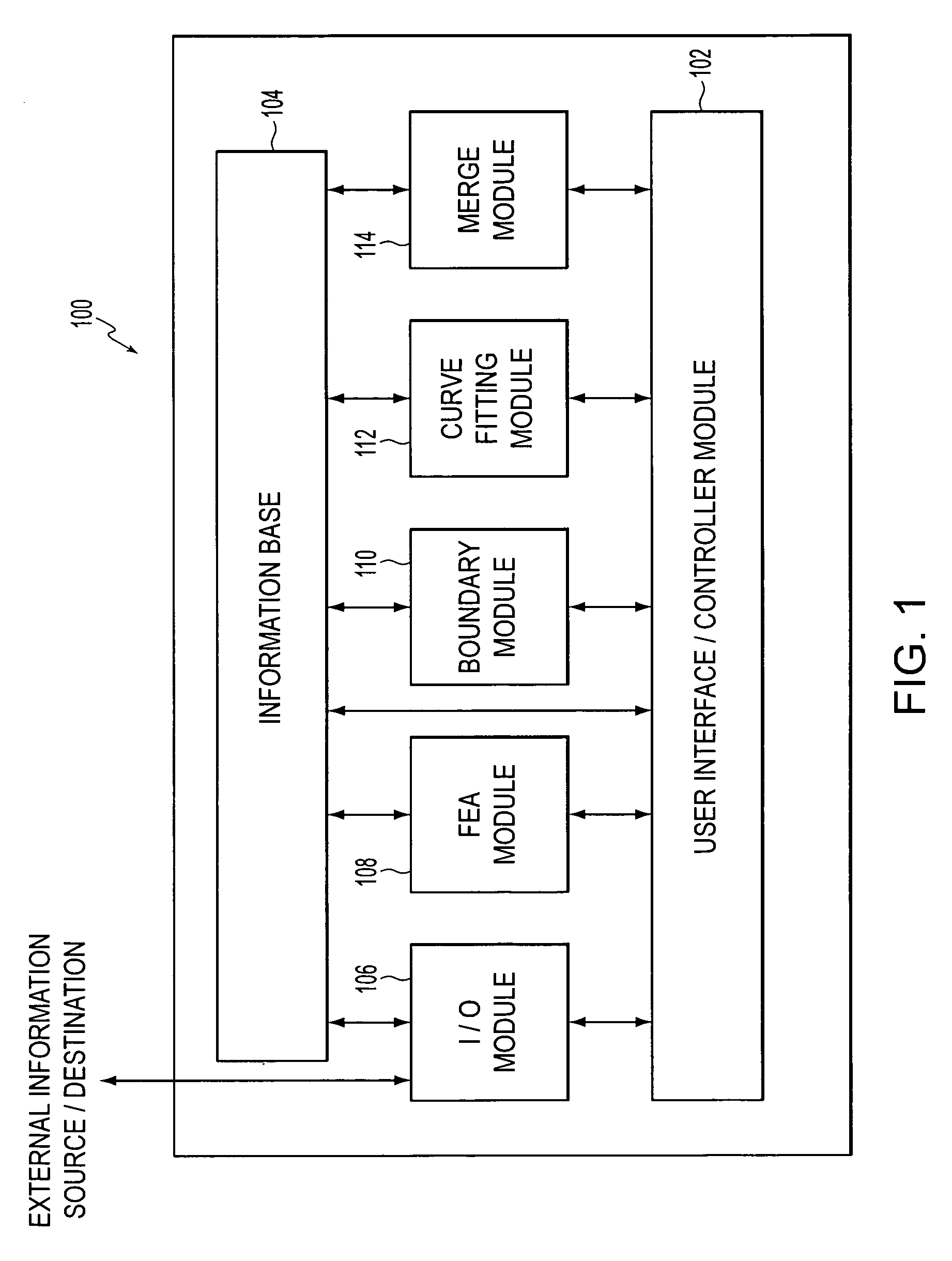
[0025]FIG. 1 presents a block diagram of a representative finite element analysis (FEA) processing system 100 that includes the contact region boundary prediction capabilities of the present invention. As shown in FIG. 1, FEA system 100 may include a user interface / controller module 102 in communication with an information base 104. FEA system 100 may further include an input / output (I / O) module 106, an FEA module 108, a boundary module 110, a curve-fitting module 112 and a merge module 114. Each of these modules may communicate with information base 104, either directly or via user interface / controller modu...


PUM


Abstract

A method and apparatus for predicting the shape of a contact region of a finite element model deformed against a contact surface. The contact surface may be a rigid body or another finite element model. The shape of a contact region is dictated by the node/element distribution in response to a simulated load. This procedure uses curve fitting to predict the boundary of a contact region for a specified load condition based upon an analysis of contact region shapes generated by finite element analysis for each load within a range of simulated loads. In this manner, the discrete nature of the contact region boundary associated with finite element analysis results at a single load is overcome using information derived from previous load simulations. The approach improves the accuracy and resolution of simulated contact shape boundaries without a corresponding increase in processing resources.

Description

BACKGROUND OF THE INVENTION [0001] 1. Field of Invention [0002] The present invention pertains to finite element analysis. In particular, the present invention pertains to smoothing finite element analysis generated tire footprints. [0003] 2. Description of Related Art [0004] A commonly recognized problem associated with conventional finite element analysis (FEA) techniques is that processor resources (e.g. dynamic memory, processing cycles, non-volatile storage, etc.), as well as processing time required to perform an FEA analysis, increase in response to increases in the FEA mesh resolution. Processor resources increase because each point of intersection of an FEA mesh applied to a finite element model represents a point for which processing, storage, and analysis is performed. Depending upon the nature of the finite element analysis to be performed, processor resources may rise significantly in response to a slight increase in the applied FEA mesh resolution. [0005] Unfortunately...

Claims


Application Information

Patent Timeline
Patent Type & Authority Applications(United States)
IPC IPC(8): G06F17/10
CPCG06F17/5095G06F17/5018G06F30/15G06F30/23
Inventor ASPER, ROBERT W.
Owner BRIDGESTONE FIRESTONE NORTH AMERICAN TIRE
Why Eureka
Try Eureka