
Engine expansion braking with adjustable valve timing

a technology of valve timing and engine expansion, which is applied in the direction of machines/engines, non-mechanical valves, machines/engines, etc., can solve the problems of increasing engine braking significantly, contributing to engine braking, and high noise emissions, so as to improve engine fuel economy, reduce combustion torque, and increase the pressure in the cylinder

Inactive Publication Date: 2006-02-16
FORD GLOBAL TECH LLC
View PDF15 Cites 14 Cited by
  • Summary
  • Abstract
  • Description
  • Claims
  • Application Information

AI Technical Summary

Benefits of technology

The present patent describes a system for controlling engine braking during deceleration and traction control in a vehicle. The system uses a Jake Brake to open the intake and exhaust valves during a portion of the compression stroke, reducing the energy recovery and increasing engine braking torque. However, this method has drawbacks such as high noise and limited braking torque. To address these issues, the patent proposes a method of controlling the valves to maintain them in a closed position during a portion of the compression stroke and then open them at a second position closer to bottom center than the first position. This approach reduces flow passing from the intake to the exhaust, resulting in lower pressure differentials and potentially less noise generation. The patent also describes various methods for controlling valve timing to optimize engine braking and performance.

Problems solved by technology

The compression and expansion of air in the cylinders during the compression and expansion stroke results in energy storage and recovery, and thus may not contribute to engine braking.
This, in turn, can increase engine braking significantly since the unrestrained expansion is dissipating energy stored during the compression stroke.
However, the inventors herein have recognized several issues with such a system.
This release of compressed gasses may cause high noise emissions due the rapid release of compressed gas.
Furthermore, the maximum amount of pressure generated by compression may be limited due to opening force requirement of the exhaust valve, thereby potentially limiting braking torque available.

Method used


Image

  • Engine expansion braking with adjustable valve timing
  • Engine expansion braking with adjustable valve timing
  • Engine expansion braking with adjustable valve timing

Examples


Embodiment Construction

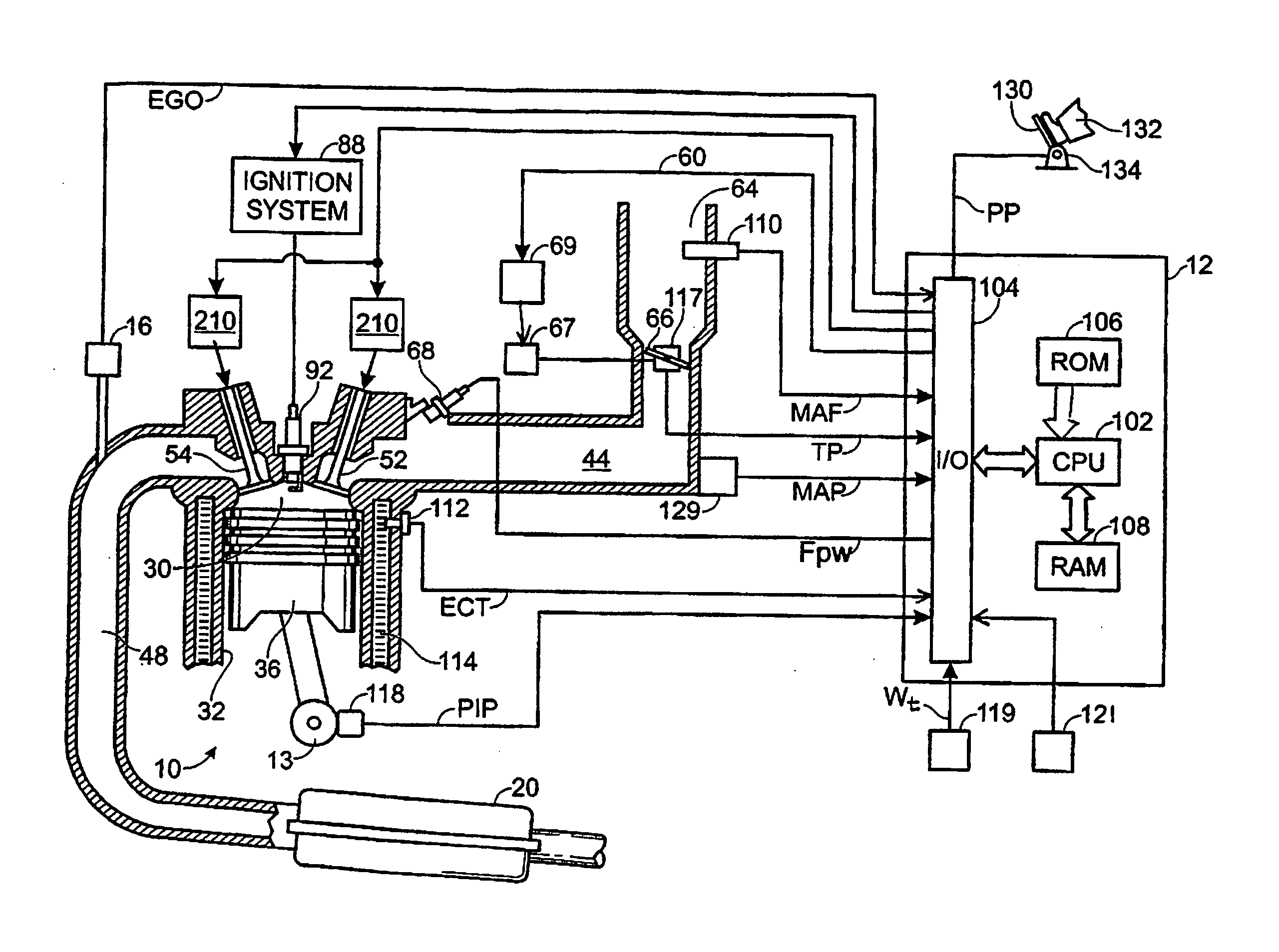
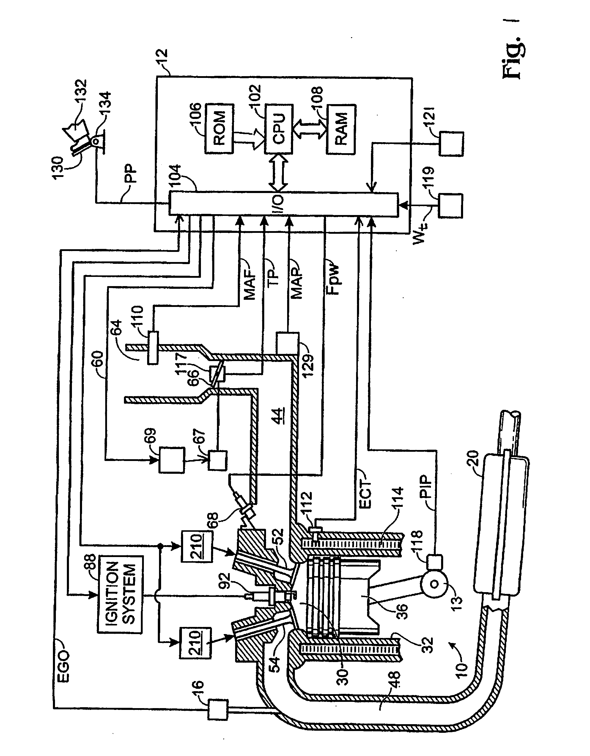
[0032] Implementation of fuel-cut operation on engines, such as deceleration fuel shut-off (DFSO), may be challenging due issues such as: [0033] (1) catalyst breakthrough and cooling issues due to lean air flow through the exhaust; [0034] (2) catalyst performance issues due to the lean exhaust gas flow that may lead to over-storage of oxygen in the exhaust, which may reduce NOx conversion; and [0035] (3) limited control of the amount of engine braking provided, which may lead to torque disturbances and reduced drive feel.

[0036] In other words, net flow through the engine may transport heat from the catalyst into the surrounding environment, which may degrade catalyst efficiency. Additionally, the engine braking characteristic may be altered if fuel-cut operation is used.

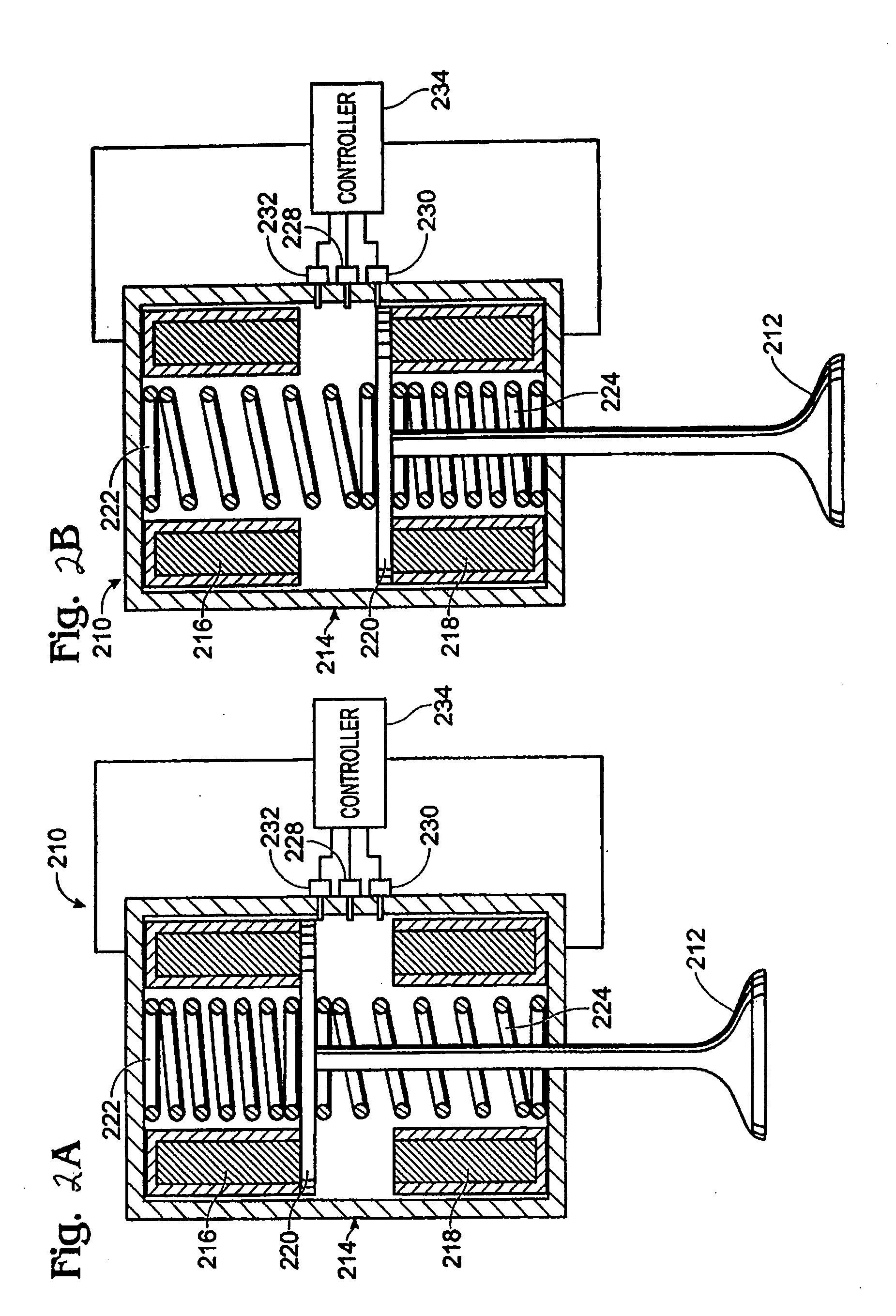
[0037] Electromechanical valve actuation (EVA) may be used with fuel-cut operation to improve performance. In other words, EVA valves on one side of the engine (intake / exhaust) may be deactivated in the closed posi...


PUM


Abstract

A system and method for controlling operation of cylinder with at least an intake and exhaust valve and a piston are described. In one aspect, the method comprises maintaining at least one of the intake and exhaust valves in a closed position during a period. Further, closing the other of the intake and exhaust valves with the piston at a first position from, and then opening the other of the intake and exhaust valves at a second position of the piston closer to bottom center than said first position, during said period.

Description

FIELD [0001] The present description relates generally to systems for controlling engine braking during deceleration and / or traction control in an internal combustion engine of a passenger vehicle traveling on the road, and more particularly to controlling opening and / or closing timing of electromechanical intake and / or exhaust valves in the engine. BACKGROUND AND SUMMARY [0002] Internal combustion engines generally produce engine output torque by performing combustion in the engine cylinders. Specifically, each cylinder of the engine inducts air and fuel and combusts the air-fuel mixture, thereby increasing pressure in the cylinder to generate torque to rotate the engine crankshaft via the pistons. One method to improve engine fuel economy during deceleration is to deactivate fuel injection to all or a selected group of cylinders to thereby reduce combustion torque and increase engine braking. [0003] The above approach can provide engine braking from engine friction and pumping wor...

Claims


Application Information

Patent Timeline
Patent Type & Authority Applications(United States)
IPC IPC(8): F02D13/04B60K28/16F01L9/20
CPCF01L9/04F02D13/04F01L2009/0469F01L2009/2169F01L9/20
Inventor MEGLI, THOMASGIBSON, ALEXMICHELINI, JOHN O.TRASK, NATEKOLMANOVSKY, ILYA V.HROVAT, DAVOR
Owner FORD GLOBAL TECH LLC
Learn More