Hydraulic opposed jet mill

a jet mill and water jet technology, applied in the field of minerals milling, can solve the problems of mica layers being broken in two and split apart, and achieve the effect of increasing the velocity of water or other incompressible liquid, and high aspect ratio of mica particles

Inactive Publication Date: 2006-02-16
KRUSE GEORGE
View PDF7 Cites 25 Cited by
  • Summary
  • Abstract
  • Description
  • Claims
  • Application Information

AI Technical Summary

Benefits of technology

[0015] A conventional positive displacement pump pumps water or other incompressible liquid into a water line at low velocity. The water line splits into two self equalizing low velocity lines and the water is introduced into the rearward portion of each of the two jets. The cross sectional area of the rearward portion of the jets is significantly greater than the cross sectional area of the forward portion of the jets. This causes the velocity of the water or other incompressible liquid to increase.
[0016] The high velocity water sprays out of the jets. Because the cross sectional area of the jets grows smaller from the rearward portion to the forward portion, the pressure of the water near the forward portion of the jets becomes sufficiently small that the relatively low pressure mineral / water slurry enters the interior of the jet and mixes with the water within the jet. The shape of the opening of the jet tends to cause the mica particles to align such that they leave the opening of the jet edge forward rather than flat side forward. Mica particles collide, edge to edge, with high energy where the jets come together in a pulverization chamber. Because the particles are align edge forward, the collisions tend to cause the layers of mica to split apart as well as being broken in two. This helps to preserve the high aspect ratio of the mica particles. The openings in the forward ends of the jets are not only opposed, but are also coplanar.

Problems solved by technology

Because the particles are align edge forward, the collisions tend to cause the layers of mica to split apart as well as being broken in two.

Method used


Image

  • Hydraulic opposed jet mill
  • Hydraulic opposed jet mill

Examples


second embodiment

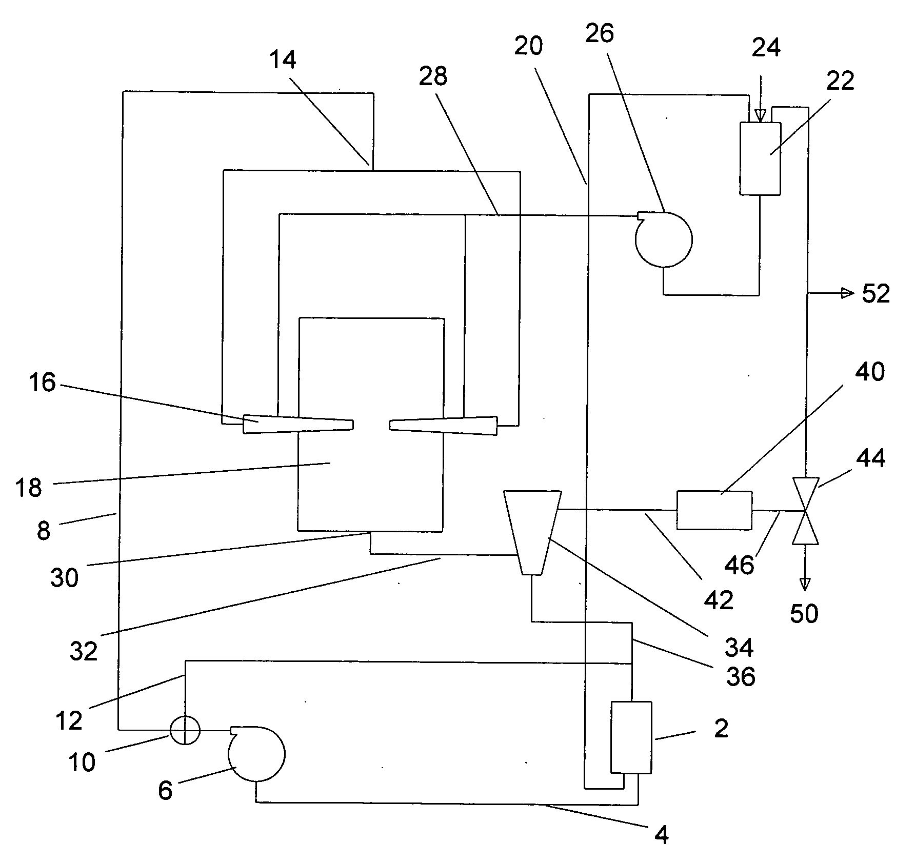
[0026] Referring to the drawings, FIGS. 1, 2 and 3, there is shown a preferred form of the hydraulic opposed jet mill of the instant invention. In the following description, mica is used to illustrate the invention, but the mill would work equally well with other minerals or materials. Water is used in the following description, but other incompressible fluids could be used if desired. The following describes an hydraulic opposed jet mill; but, in a second embodiment, rather than having opposed jets, the mill would employ one or more jets which were not opposed, but directed toward an impact or impingement plate.

[0027] Now referring to FIG. 1, a schematic drawing of the hydraulic jet mill process of the instant invention is shown. A water supply tank 2 is connected to a water supply line 4. A positive displacement pump 6 pumps water at from 6 to 500 gallons per minute from the water supply tank 2 into a low velocity water line 8. Although the above flow rate range was found to inclu...

third embodiment

[0033] In a third embodiment, the centrifuge 34 is replaced by a conventional wet filter. With this wet filter the slurry is pressed through the filter and the slurry can be separated into slurry with nano sized particles and slurry with greater than nano sized particles. After separation, both slurries may be shipped and sold as is or the greater than nano sized particles slurry may be recycled through either said water supply tank 2 for nonabrasive materials or at 24 for abrasive materials.

fourth embodiment

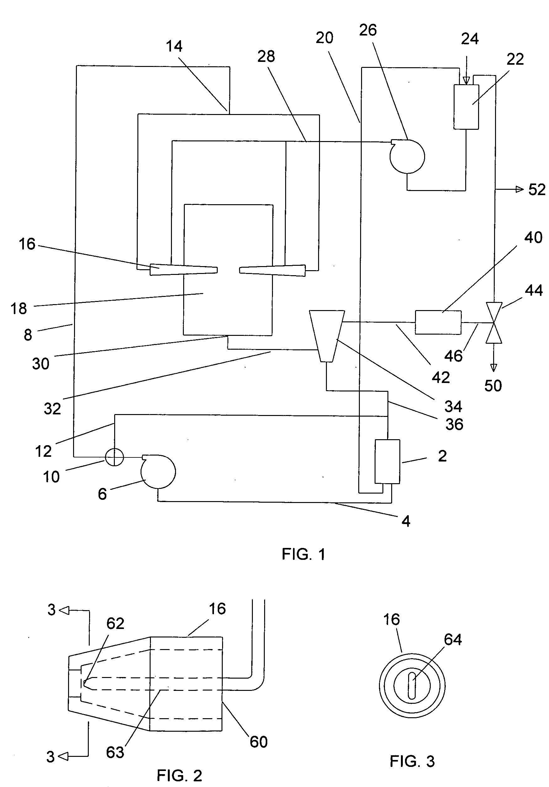
[0034] In a fourth embodiment, said orifice 64 is not elongated. Instead, a pair of opposed vanes is affixed to the outer surface of said jet 16 such that the material / liquid slurry is forced into the shape of a thin fan upon exiting said orifice 64.

[0035] In the preferred embodiment, all elements are conventional and may be secured from a variety of sources with the exception of said jets 16. Said jets 16 are manufactured from an alloy such as AR steel, Ni-hard steel, or a ceramic which is very resistant to abrasion. All elements which transport slurry are also made from abrasion resistant material.


PUM


Abstract

Embodiments of an hydraulic opposed jet mill are disclosed which may be used to crush various minerals, including mica, or other materials to sub-micron size. At least one positive displacement pump forces an incompressible liquid, such as water, through a pair of opposed jets such that the two streams of water collide between the jets. A slurry of an incompressible liquid, such as water, and the mineral to be crushed is introduced into the jets at a point near the outlet end of the jets. The entrained mineral particles are forced out of the jets with great energy which causes multiple collisions and pulverization. In a second embodiment of the instant invention the slurry strikes an impingement plate rather than an opposed slurry stream.

Description

RELATED APPLICATIONS [0001] This application relies for priority upon the Provisional Patent Application filed by George Kruse entitled Hydraulic opposed jet mill, Ser. No. 60 / 602,029, filed Aug. 16, 2004.BACKGROUND OF THE INVENTION [0002] 1. Field of the Invention [0003] The present invention relates generally to the milling of minerals and more specifically to milling by shooting opposed jets of mineral and a carrying medium into one another. [0004] 2. Background Information [0005] For hundreds of years, mankind has struggled to develop methods of reducing the size of ore and other minerals. Dozens of different types of mills have been invented to crush or mill minerals. In a hammer mill, for example, a series of “hammers” literally pound the material to crush it to a smaller size. Most often, after milling, the material is sized usually using one or more screens. Material which passes through a screen having the appropriate mesh size is usually sold or used in a manufacturing pro...

Claims


Application Information

Patent Timeline
Patent Type & Authority Applications(United States)
IPC IPC(8): B02C21/00
CPCB02C23/12B02C19/065
Inventor KRUSE, GEORGE
Owner KRUSE GEORGE
Why Eureka
Try Eureka