
Hydraulic shaft sealing arrangement for high-temperature applications

a technology of hydraulic shaft and sealing arrangement, which is applied in the direction of engine sealing, climate sustainability, sustainable transportation, etc., can solve the problems of affecting the performance of the aircraft engine, the lubricant of the two shaft bearings, and the oil used, so as to reduce the hazard of coking, improve the continuity of exchange of the entire sealing medium, and minimize the temperature of the sealing medium. , the effect of reducing the temperatur

Active Publication Date: 2006-02-16
ROLLS ROYCE DEUT LTD & CO KG
View PDF5 Cites 15 Cited by
  • Summary
  • Abstract
  • Description
  • Claims
  • Application Information

AI Technical Summary

Benefits of technology

The present invention provides a hydraulic shaft sealing arrangement that prevents oil carbon formation, ensures reliable sealing at all times, saves space, weight, and assembly time, and ensures rapid oil exchange. The arrangement includes a heat protection ring and a separate annulus for the sealing medium, which is formed by two annular disks and an angular ring. The arrangement also includes means for improving the continuous exchange of the sealing medium, such as pumping action and a thermally insulating air chamber / stagnation zone, which reduces the temperature of the sealing medium and the hazard of coking. The invention also provides a simplified assembly process and a design that facilitates the scavenging of the hottest, most readily coking sealing medium.

Problems solved by technology

In high-temperature applications, specifically the sealing of the bearing chamber for the high-pressure shaft and the low-pressure shaft of a gas turbine engine against the compressor air supplied at a temperature of 400° C., for example, these hydraulic sealing arrangements are problematic in that the oil, which is used as sealing medium and lubricant of the two shaft bearings, is liable to degradation and coking as a result of the high temperatures.
The considerable overall size and high weight of this design result in the known disadvantages for an aircraft engine.
Removal of the sealing medium from an annulus area formed into the bottom is, however, disadvantageous in that sealing against the hot high-pressure zone will be affected if the supply of oil and, thus, the amount of sealing medium in the annulus is inadequate.

Method used


Image

  • Hydraulic shaft sealing arrangement for high-temperature applications
  • Hydraulic shaft sealing arrangement for high-temperature applications

Examples


Embodiment Construction

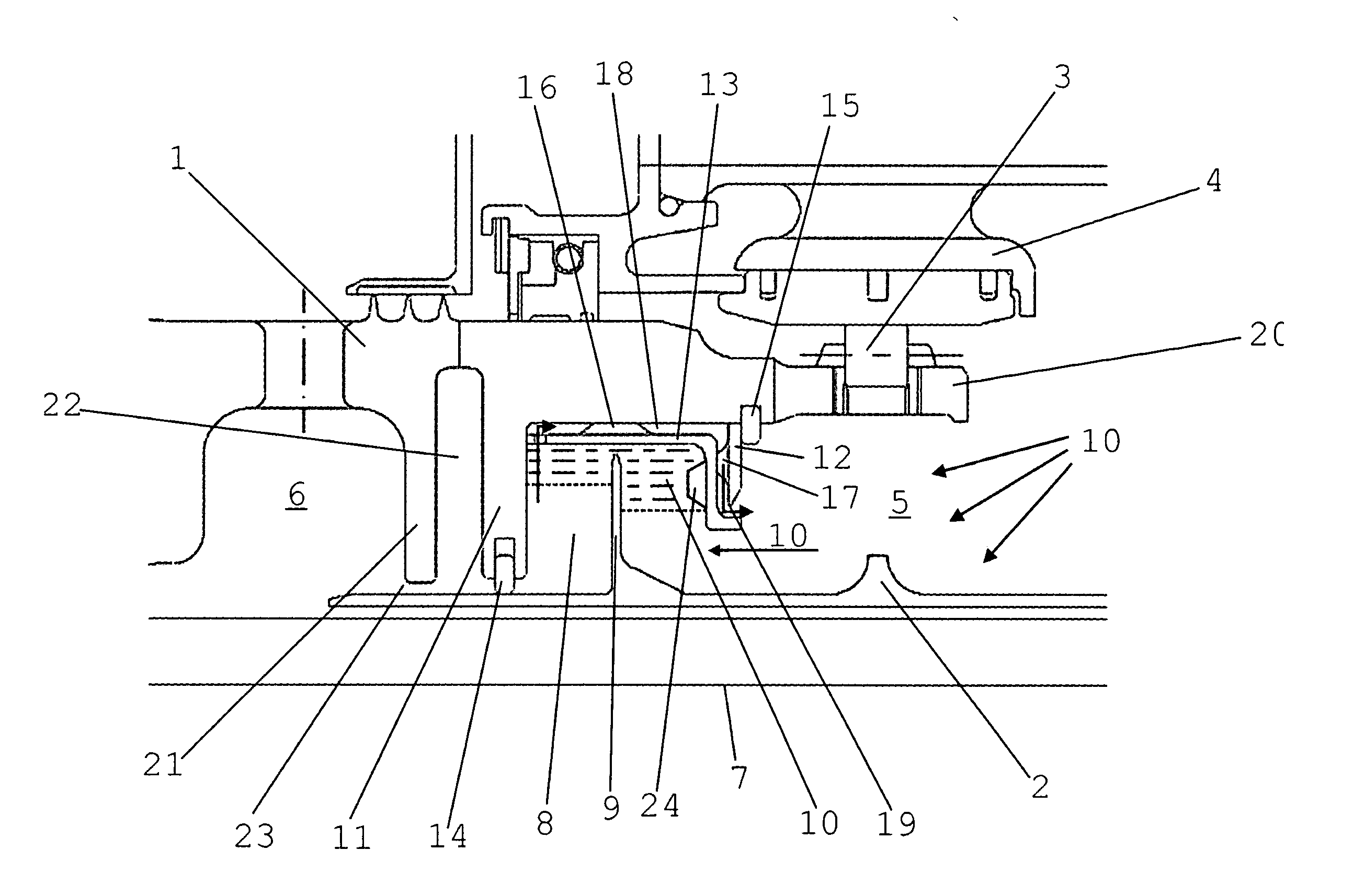
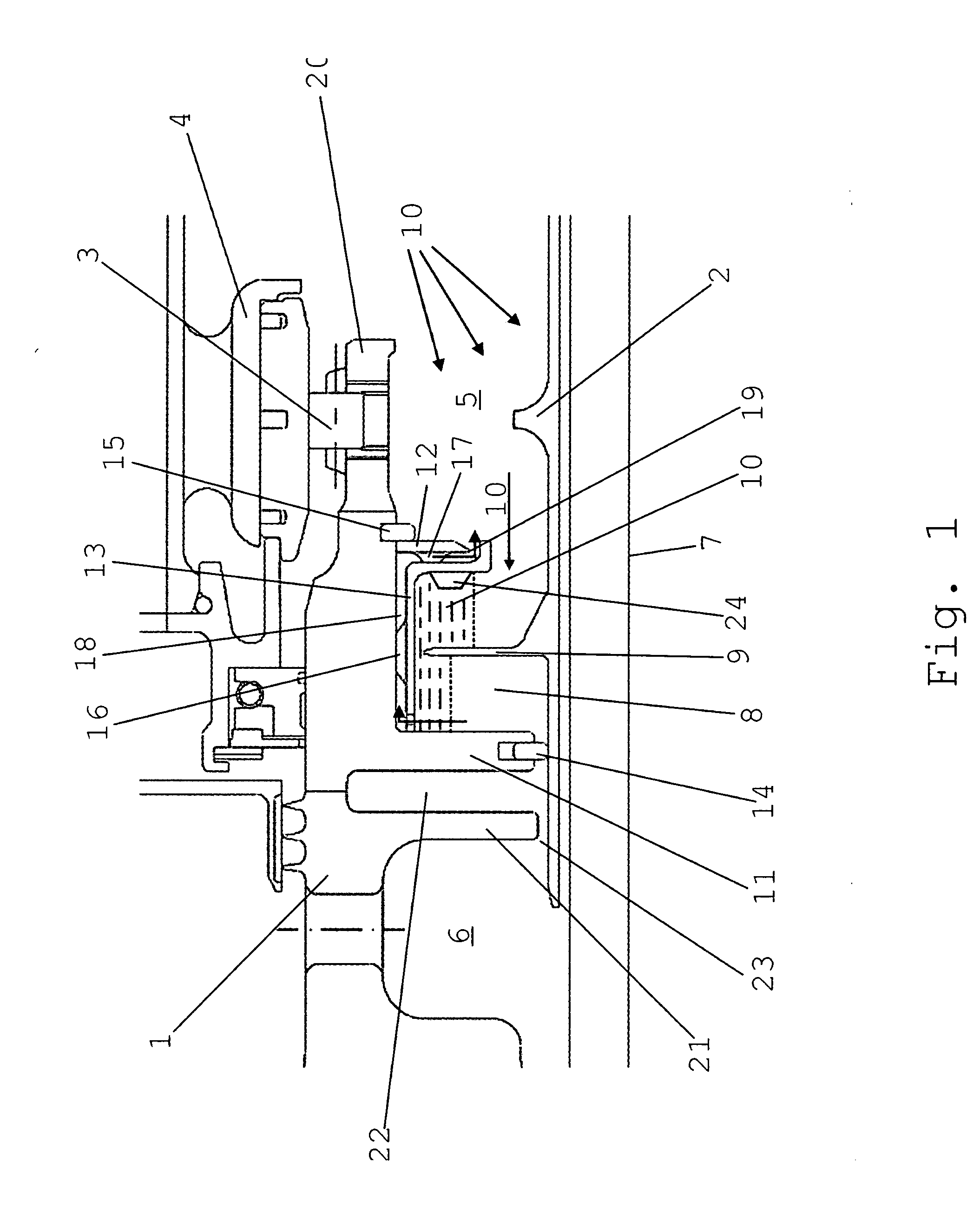
[0013] The high-pressure shaft 1 and the low-pressure shaft 2 of a gas turbine engine are concentrically supported in the turbine casing 4 by means of a first rolling bearing 3 for the high-pressure shaft 1 and a second rolling bearing (not shown) for the low-pressure shaft 2. For cooling and lubrication, the bearing chamber 5 so formed is continuously supplied with coolant-lubricant (oil). In order to seal the low-pressure zone in the bearing chamber 5 against the relatively hot high-pressure zone 6 to avoid coking and ignition of the oil, the two, preferably co-rotating shafts, here the high-pressure shaft 1 and the low-pressure shaft 2, are sealed against each other by means of a hydraulic sealing arrangement. The hydraulic sealing arrangement comprises an U-shaped annulus 8 provided on the high-pressure shaft 1 and open to the rotational axis 7 which, as a result of the centrifugal forces effected by the rotation of the high-pressure shaft 1, is filled with coolant-lubricant sup...


PUM


Abstract

On a hydraulic shaft sealing arrangement for high-temperature applications, a heat protection ring (21) and an air chamber (22) are arranged before the annulus (8) containing the sealing medium (10) for thermal insulation, while spacers (16, 17) for the generation of a pumping action are provided in the annulus continuously supplied with fresh sealing medium (oil) to accelerate liquid transport. The hazard of coking and oil carbon deposition is thereby minimized. A split design of the annulus with an inserted annular ring also provides for an improved hydraulic shaft sealing arrangement optimized for weight, overall height, manufacture and assembly time.

Description

[0001] This application claims priority to German Patent Application DE 10 2004 040 242.6 filed Aug. 13, 2004, the entirety of which is incorporated by reference herein. BACKGROUND OF THE INVENTION [0002] This invention relates to a hydraulic shaft sealing arrangement for high-temperature applications, more particularly for concentric shafts of a gas turbine engine, to seal the high-pressure shaft bearing chamber located in the low-pressure zone and the low-pressure shaft against the high-pressure zone. [0003] Hydraulic sealing arrangements, as is generally known, are used for contact-free sealing between two concentric, co-rotating shafts. In principle, such sealing arrangements can also be used with only one rotating shaft. The sealing arrangement normally consists of an essentially U-shaped annulus arranged on the inner circumference of the outer shaft which is filled with a fluidic sealing medium, preferably oil, supplied from the lubricating circuit of the respective engine by ...

Claims


Application Information

Patent Timeline
Patent Type & Authority Applications(United States)
IPC IPC(8): F16J15/40
CPCF01D11/04Y02T50/671F16J15/42F01D25/183Y02T50/60
Inventor GAEBLER, MIKLOSHEIN, STEFAN
Owner ROLLS ROYCE DEUT LTD & CO KG
Learn More