Wireless LAN network system and a method for connecting access points thereof

a wireless lan and access point technology, applied in the field of wireless lan systems, can solve the problems of affecting the determination of unique communication paths, cumbersome setting requirements in the introduction stage, and affecting the service area of wireless lans, etc., and achieves the effect of simple procedure, effective and convenient operation

Inactive Publication Date: 2006-02-16
IWATSU ELECTRIC CO LTD
View PDF7 Cites 33 Cited by
  • Summary
  • Abstract
  • Description
  • Claims
  • Application Information

AI Technical Summary

Benefits of technology

[0033] The present invention allows for extension of the service area of a wireless LAN through a simple procedure, thereby providing a very effective means for building an economical, easy-to-use wireless LAN.

Problems solved by technology

However, the settings required in the introduction stage are cumbersome and give significant burdens to the installation manager.
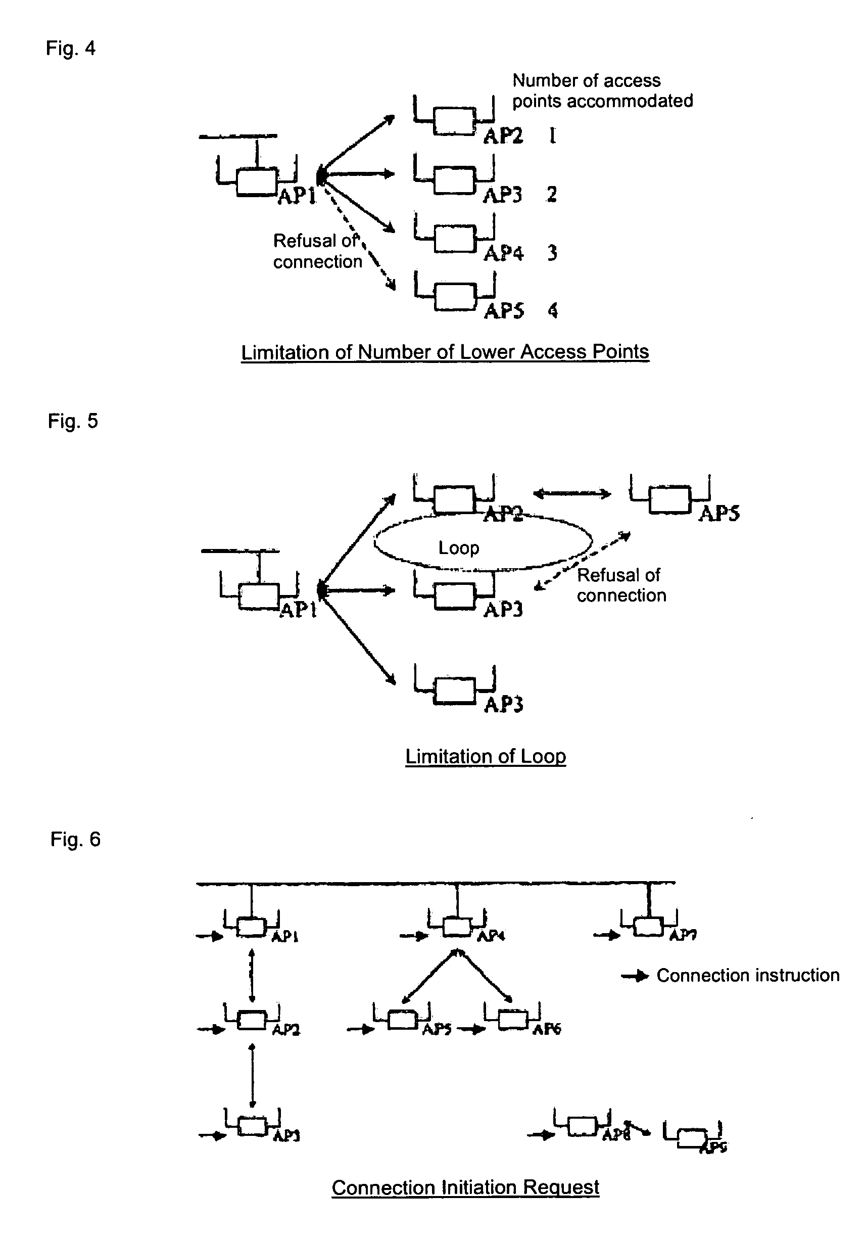
Additionally, allowing multiple access points to interconnect with one other forms loops in the network, which interferes with the determination of unique communication paths.
However, this technology sends information packets into the network on a regular basis and thereby consumes the bandwidth of the wireless LAN network.
Also, a mobile station performs registration processing (handover processing) at each new access point to which it moves, so movement of the mobile station during communication may temporarily disconnect the communication.

Method used


Image

  • Wireless LAN network system and a method for connecting access points thereof
  • Wireless LAN network system and a method for connecting access points thereof
  • Wireless LAN network system and a method for connecting access points thereof

Examples


Embodiment Construction

[0069]FIG. 19 shows a block diagram of an access point in which the aforementioned functions are installed. The access point comprises the access point control unit (4), memory (5), send / receive unit (2), wireless LAN port (1), wired LAN port (3) and switch (6). The wireless LAN port (1) receives the packets sent to the wireless LAN network and sends the packets from the send / receive unit to the wireless LAN network. The wired LAN port (3) receives the packets sent to the wired network and sends the packets from the send / receive unit to the wired network. The send / receive unit (2) transfers to the wireless LAN port (1) / wired LAN port (3) or access point control unit (4), in accordance with the instruction by the access point control unit (4), the packets transferred from the access point control unit (4) or wireless LAN port (1) / wired LAN port (3). The access point control unit (4) references the “connection relationship information” in the memory (5) and performs connection control...


PUM


Abstract

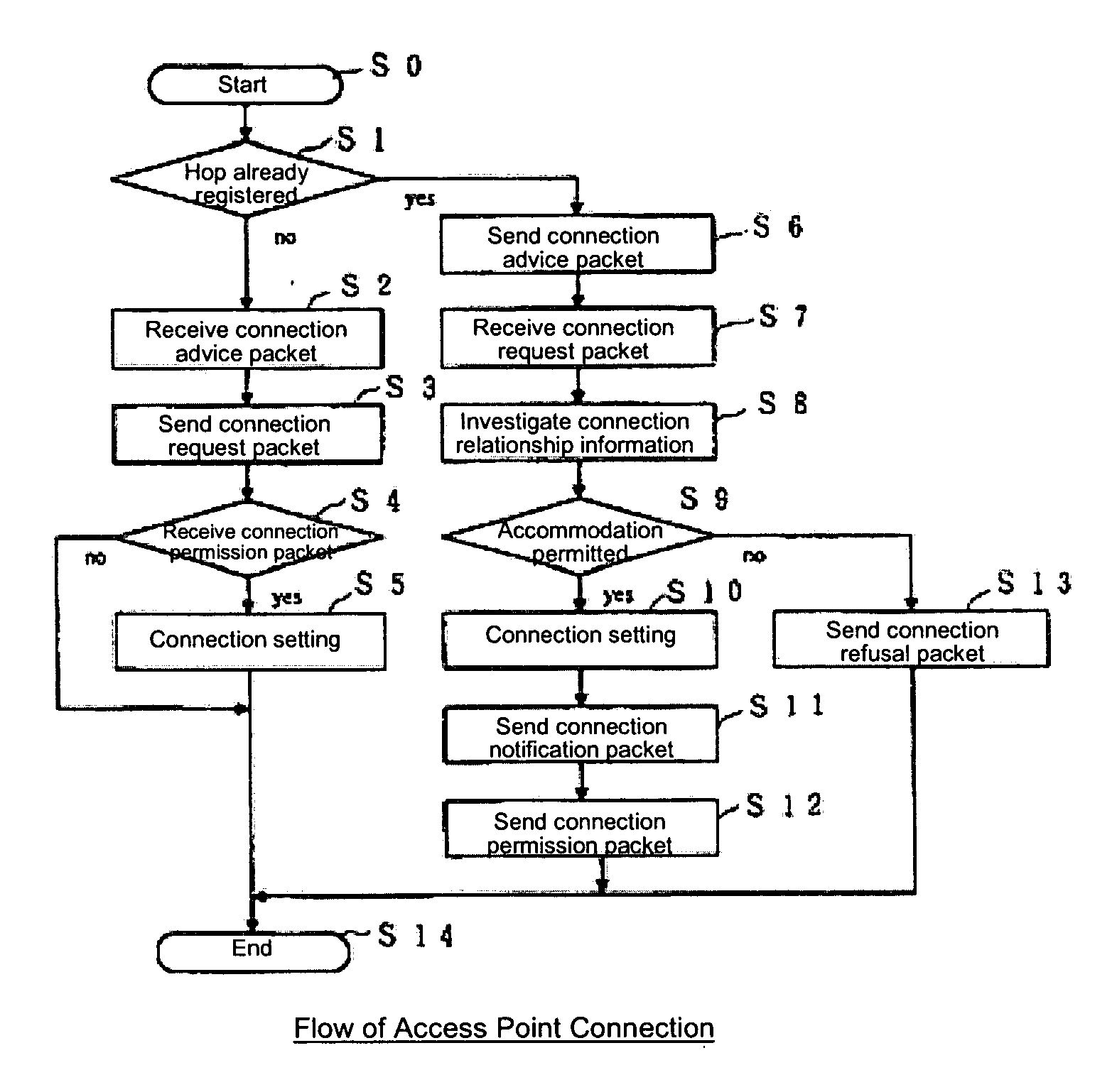
Each access point determines the LAN cable insertion status and acts as the master access point if a cable is inserted, or as the slave access point if no cable is connected. Of the two access points receiving a “connection instruction,” the master access point or a upper access point connected directly or indirectly to the master access point sends a “connection advice message” from the higher level, the lower access point not connected to the master access point sends a “connection request message” from the lower level, and then a “connection response message” is sent from the higher level, and through this procedure the lower access point is added to a new service area.

Description

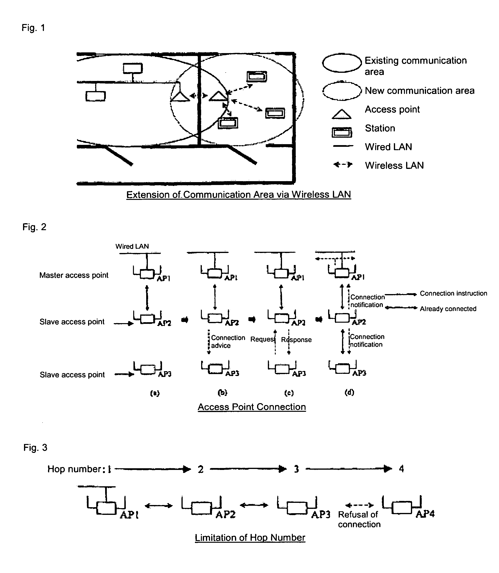
BACKGROUND OF THE INVENTION [0001] 1. Field of the Invention [0002] This invention relates to a wireless LAN system used for extending the communication area and increasing the handover speed. [0003] 2. Description of the Related Art [0004] To extend the communication area of a local area network (LAN), a wireless LAN access point is installed in the current communication area as well as in the new area to establish communication with. Then, by setting the MAC address of each access point in the other access point, communication between the two access points via a wireless LAN becomes possible. When a mobile station is installed in the new communication area and registered to the access point in the new area, the mobile station can communicate with the current communication area via the two access points (FIG. 1). This method using a wireless LAN is generally referred to as the access point interconnection system or WDS (Wireless Distribution System) (refer to IEEE Standard 802.11, ...

Claims


Application Information

Patent Timeline
Patent Type & Authority Applications(United States)
IPC IPC(8): H04Q7/24H04W76/02H04W84/12H04W92/20
CPCH04W24/02H04W92/20H04W84/12H04W84/045
Inventor YAMANE, KOJI
Owner IWATSU ELECTRIC CO LTD
Why Eureka
Try Eureka