Carrier synchronization to reduce common mode voltage in an AC drive

a common mode voltage and carrier synchronization technology, applied in the direction of transmission, transmission monitoring, pulse technique, etc., can solve the problems of drive and load bearing failure, particularly adverse effects on configuration components, and debroe does not teach or suggest a specific way in which to synchronize carrier frequency and phas

Inactive Publication Date: 2006-02-16
ROCKWELL AUTOMATION TECH
View PDF10 Cites 56 Cited by
  • Summary
  • Abstract
  • Description
  • Claims
  • Application Information

AI Technical Summary

Benefits of technology

[0021] At least some embodiments include a method for use with a power conversion configuration including a pulse width modulated (PWM) converter and a PWM inverter wherein a master PWM frequency signal for one of the converter and inverter and a slave PWM frequency signal for the other of the converter and the inverter are provided and wherein PWM signals for controlling the first converter and first inverter are derived by comparing converter and inverter modulating waveforms to converter and inverter carrier signals, respectively, the method for substantially synchronizing inverter and converter carrier signals and comprising the steps of generating a master carrier count as a function of the master PWM frequency signal wherein the master carrier count counts up from a minimum master counter value to a maximum master counter value and down from the maximum master counter value to the minimum master counter value, generating a slave carrier count as a function of the slave PWM frequency signal wherein the slave carrier count counts up from a minimum slave counter value to a maximum slave counter value and down from the maximum slave counter value to the minimum slave counter value, identifying a phase difference between the master and slave counter values, using the phase difference to modify subsequent slave carrier counts and using the master carrier count and the modified slave carrier count to generate converter and inverter PWM control signals.
[0022] Some embodiments include a method for use with a power conversion configuration including a pulse width modulated (PWM) converter, a PWM inverter and master and slave carrier signal generators wherein the master and slave carrier signal generators receive master and slave PWM frequency signals and generate master and slave carrier signals as a function thereof, PWM signals for controlling the converter and the inverter derived by comparing converter and inverter modulating waveforms to converter and inverter carrier signals, respectively, the method comprising the steps of identifying a phase difference between the master and slave carrier signals, using the phase difference to modify subsequent slave carrier signals to substantially conform the slave carrier signal frequency and phase to the master carrier signal frequency and phase and using the master carrier signal and the modified slave carrier signal to generate control signals for the converter and the inverter.

Problems solved by technology

564-568 in 1996 describes how common mode voltages (CMVs) occur within a convert-inverter-load configuration that can generally lead to drive and load bearing failures.
Specifically, the DeBroe article recognizes that if linked inverters and converters are switched such that all of the inverter legs are linked to the positive DC bus while all of the converter legs are linked to the negative DC bus or vice versa (i.e., such that different zero voltage vectors simultaneously result in the inverter and the converter), CMVs as high as the DC bus voltage can result which have particularly adverse affects on configuration components.
While the DeBroe article suggests a general solution for reducing high CMV, DeBroe does not teach or suggest a specific way in which to synchronize carrier frequencies and phase.
While this solution works in theory, most inverter and converter sub-assemblies already come equipped with their own signal generators and are not designed for their internally generated carrier signals to be bypassed.
In many converter sub-assemblies that internally generate carrier counts the carrier counts cannot be bypassed.
Unfortunately, even where the command frequencies provided to two carrier signal generators are identical, it has been observed that small differences in crystals result in drift between the resulting carrier counts.
As drift accumulates, at times carrier counts that may have initially been seemingly in phase are completely out of phase and high CMVs result.

Method used


Image

  • Carrier synchronization to reduce common mode voltage in an AC drive
  • Carrier synchronization to reduce common mode voltage in an AC drive
  • Carrier synchronization to reduce common mode voltage in an AC drive

Examples


Embodiment Construction

[0033] One or more specific embodiments of the present invention will be described below. It should be appreciated that in the development of any such actual implementation, as in any engineering or design project, numerous implementation-specific decisions must be made to achieve the developers' specific goals, such as compliance with system-related and business related constraints, which may vary from one implementation to another. Moreover, it should be appreciated that such a development effort might be complex and time consuming, but would nevertheless be a routine undertaking of design, fabrication, and manufacture for those of ordinary skill having the benefit of this disclosure.

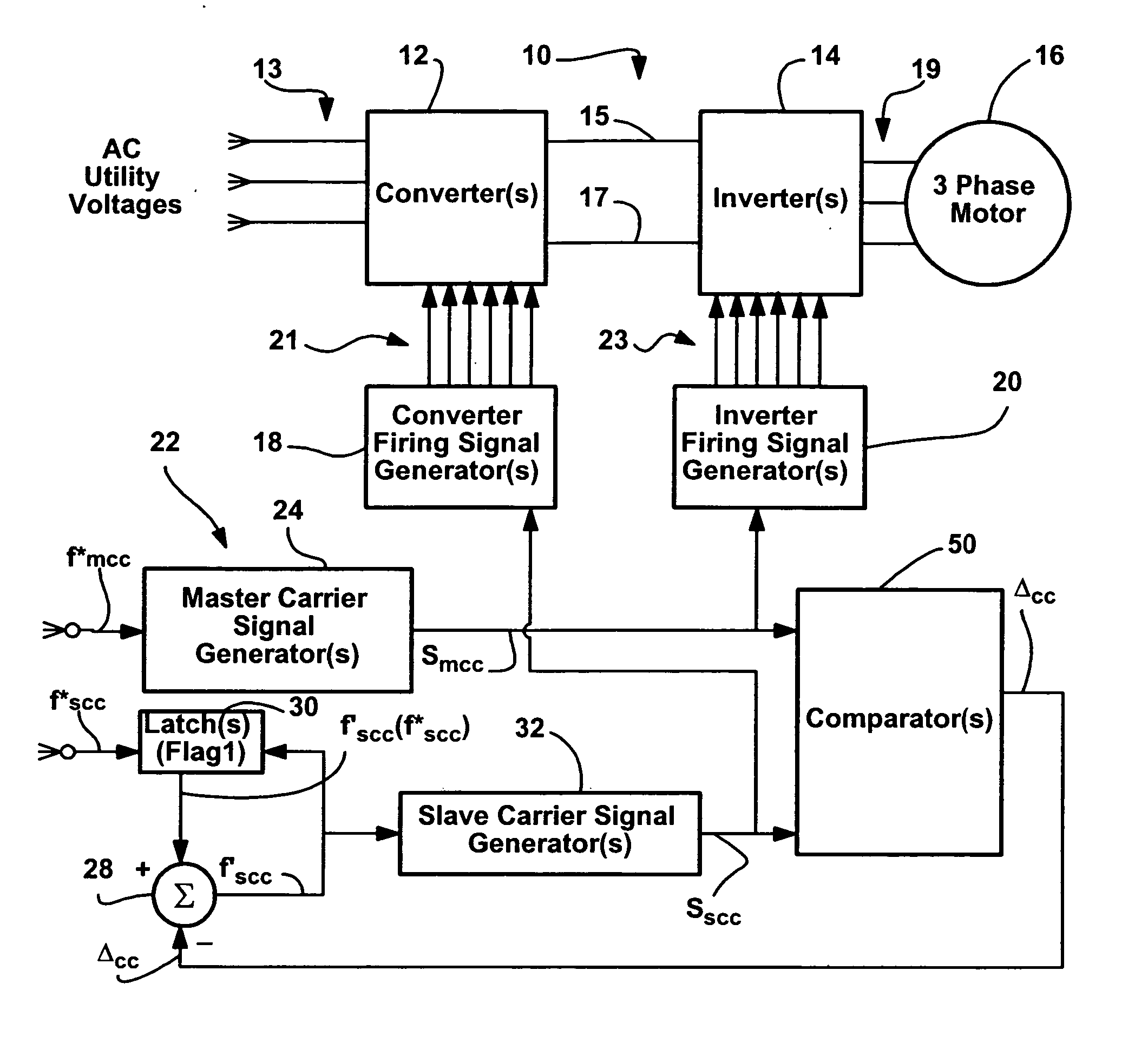
[0034] Referring now to the drawings wherein like reference numerals correspond to similar elements throughout the several views and, more specifically, referring to FIG. 1, the present invention will be described in the context of an exemplary power conversion configuration 10 including a converter ...


PUM


Abstract

A method and apparatus for use with a power conversion configuration including a pulse width modulated (PWM) converter, a PWM inverter and master and slave carrier signal generators wherein the master and slave carrier signal generators receive master and slave PWM frequency signals and generate master and slave carrier signals as a function thereof, PWM signals for controlling the converter and the inverter derived by comparing converter and inverter modulating waveforms to converter and inverter carrier signals, respectively, the method comprising the steps of identifying a phase difference between the master and slave carrier signals, using the phase difference to modify subsequent slave carrier signals to substantially conform the slave carrier signal frequency and phase to the master carrier signal frequency and phase and using the master carrier signal and the modified slave carrier signal to generate control signals for the converter and the inverter.

Description

CROSS-REFERENCE TO RELATED APPLICATIONS [0001] Not applicable. STATEMENT REGARDING FEDERALLY SPONSORED RESEARCH OR DEVELOPMENT [0002] Not applicable. BACKGROUND OF THE INVENTION [0003] This invention relates generally to power conversion configurations and more specifically to power conversion configurations that includes at least one AC-DC converter and one DC-AC inverter where a separate oscillator crystal generates carrier signals for each of the inverters and converters and where the carrier signals are synchronized to reduce common mode voltage within the configuration. [0004] One type of widely employed AC-AC power conversion configuration includes at least one active three phase converter sub-assembly and at least one three phase inverter sub-assembly. The converter sub-assembly is linked to three phase AC lines and receives voltages thereon from a power grid and converters those voltages to a DC voltage across positive and negative DC buses. The inverter sub-assembly is link...

Claims


Application Information

Patent Timeline
Patent Type & Authority Applications(United States)
IPC IPC(8): H04B17/00H03K9/08H02M7/5387
CPCH02M5/458H02P27/08H02M7/53871H02M5/4585H02M1/123
Inventor BREITZMANN, ROBERT JOHNJENKS, JOHN JAMESKASUNICH, JOHN M.
Owner ROCKWELL AUTOMATION TECH
Why Eureka
Try Eureka