Remote meter reading using transmitted visual graphics.

a technology of transmitted visuals and meter readings, applied in the direction of volume metering, liquid/fluent solid measurement, instruments, etc., can solve the problems of complex automatic meter reading devices, high cost, complex and expensive process, etc., to reduce the operating cost of meter readings, increase the capability of meter readings, and avoid costly operations

Inactive Publication Date: 2006-02-16
CRICHLOW HENRY B
View PDF7 Cites 59 Cited by
  • Summary
  • Abstract
  • Description
  • Claims
  • Application Information

AI Technical Summary

Benefits of technology

[0055] Another specific objective is to provide a novel system wherein operational costs associated with meter reading can be minimized since manual meter reading, ride-by reading and drive-by reading are no longer required.
[0056] Another specific objective is to implement an improved means of increasing the meter's capability by allowing the meter data to be stored at a local RMR device for example an adjacent electric meter device, before being transmitted to the host computer.
[0057] Another objective is to implement accepted algorithmic processes in the software image analyzer such as, ANN, Fuzzy Logic, OCR in such a manner without having to make major capital investments in expensive and computationally difficult mathematical program like digitizing of video feeds and streaming video data with costly operations.

Problems solved by technology

In a very expensive and complicated process, the video signal is then digitized by a data interface, which is calibrated for the meter environment.
Patent GB 2,345,566 provides an integrated, complex and expensive automatic meter reading device, comprising an imaging section connected to a character recognizing section for recognizing the contents of the display section which are imaged by the imaging section.

Method used


Image

  • Remote meter reading using transmitted visual graphics.
  • Remote meter reading using transmitted visual graphics.
  • Remote meter reading using transmitted visual graphics.

Examples


Embodiment Construction

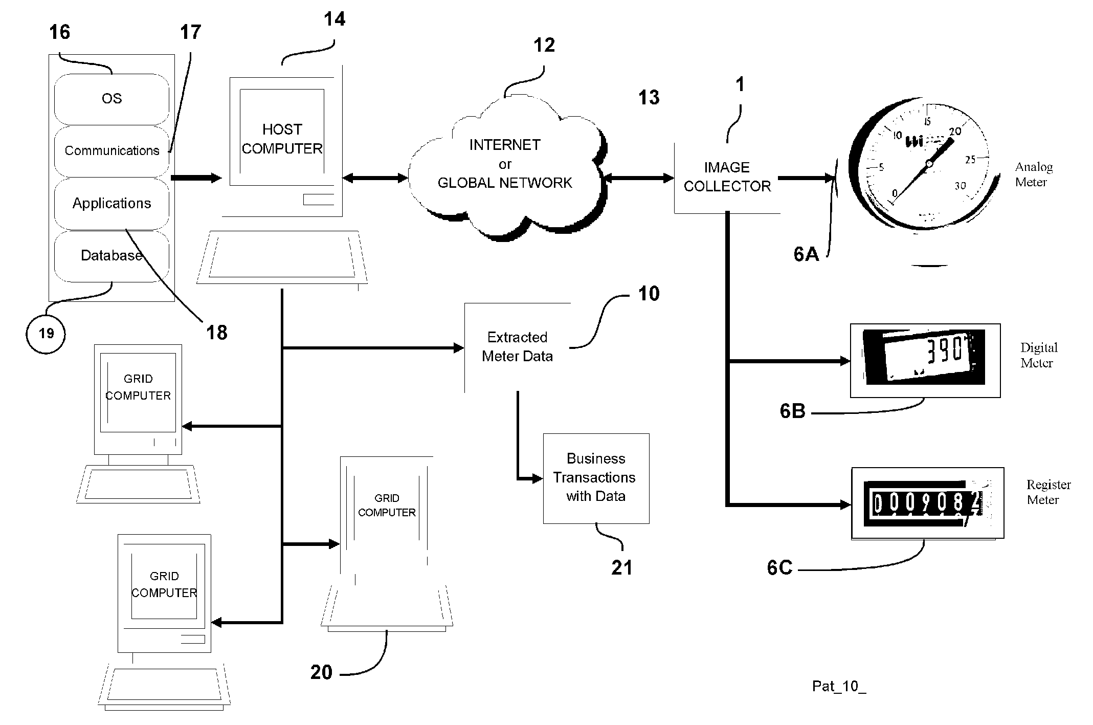
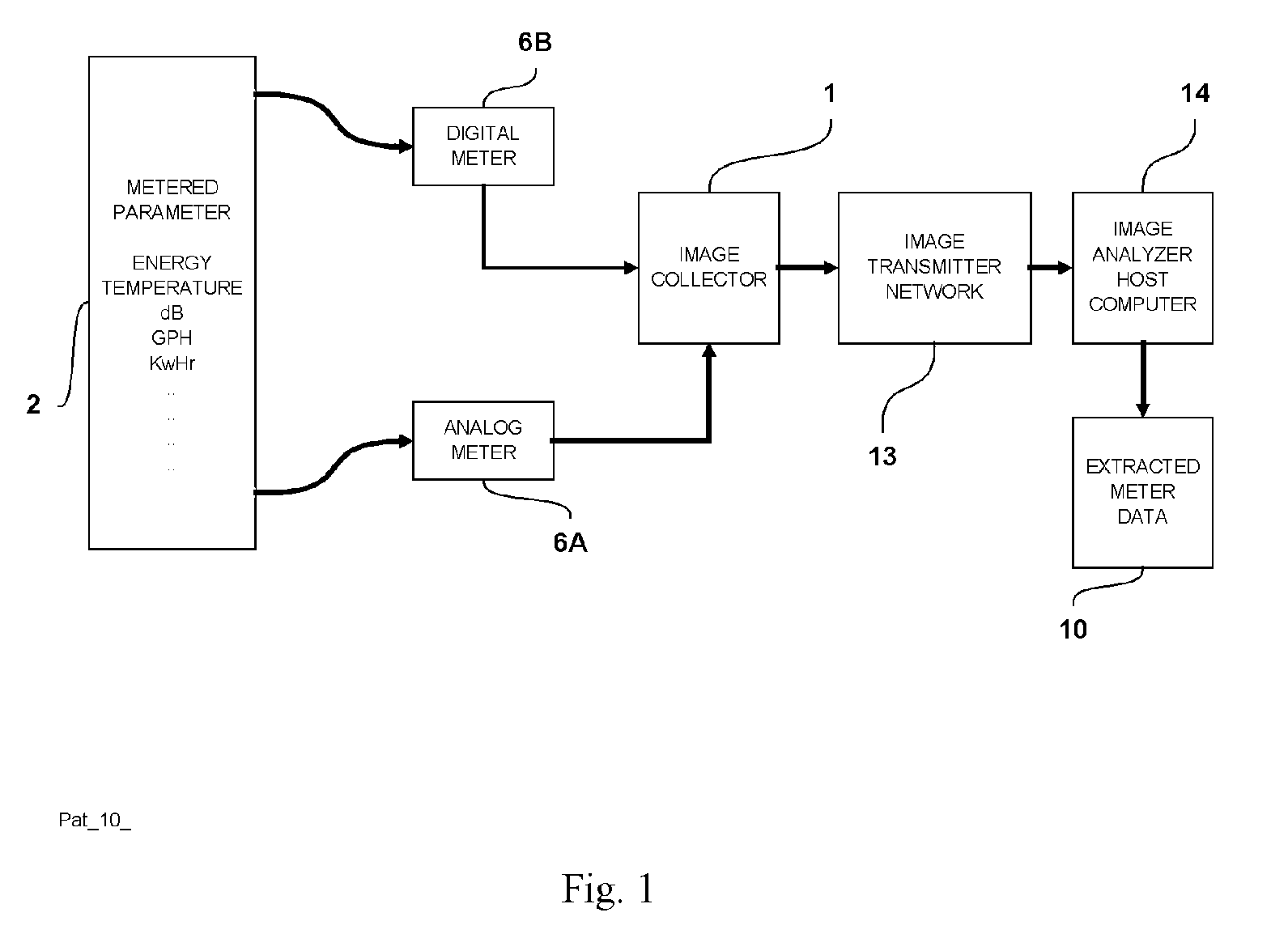
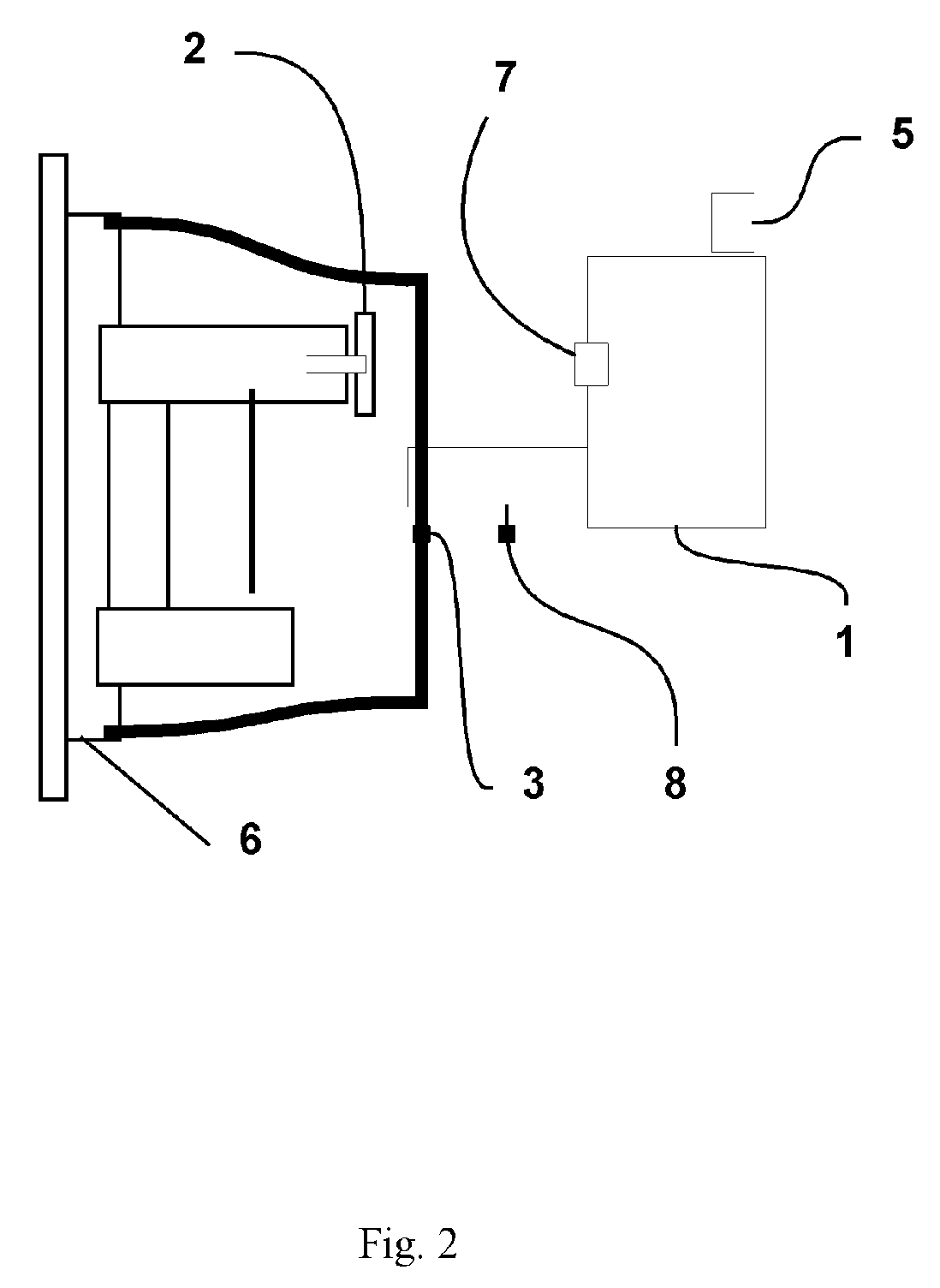
[0075] A preferred embodiment of the techniques of the present invention of “visual-metering” will now be described in the context of a typical RMR operation. Those skilled in the art, however, will recognize that the central ideas of the invention are not limited to the details enumerated below. Over the years meter reading has been made manually by human meter readers who literally walk the line and read each meter. Changes have allowed some companies to read meters by using special meters equipped with radio frequency transponders, which are both expensive and bulky to read meters; by “drive-by” operations using an antenna equipped truck. There are many systems with dedicated communication lines either wired, wireless, CATV, DSL or radio communication systems. The fundamental need is to get the meter reading data to the utility or operator as cheaply and as quickly as possible.

[0076] RMR needs are simple. Electric, gas, water and other utilities and other operators require a rel...


PUM


Abstract

A technique for remote meter reading (RMR) of a plurality of meters uses visual image devices coupled to pattern recognition technologies to allow unattended meters, gages, registers, screens, and other similar display equipment to communicate their output data without human intervention to a central source and to provide this data on a global network. Historically, meters, gages and similar devices were either read by the human eye or by data-loggers and controllers which transmitted these data to a host system. With this invention the display devices can be read autonomously by the method described herein and a visual graphic of the meter face is transmitted to a host which then recognizes the data value embedded in the visual. Substantial increases in efficiency; performance and economics can be achieved with this invention which introduces the concept of “visualmetering”.

Description

CROSS REFERENCE TO RELATED APPLICATIONS [0001] This application claims priority from provisional application No. 60 / 564,991 filed Apr. 26, 2004 by the inventor, Henry Crichlow. This application is related to application Ser. No. 10 / 016,049 filed Dec. 12, 2001, application Ser. No. 10 / 033,667, filed Dec. 27, 2001 and application Ser. No. 60 / 564,991 filed Apr. 26, 2004 filed by the inventor.[0002] Normally, energy consumption devices shown in FIGS. 1 and 2 have to be read on a regular basis for billing and other operational purposes. This technology described herein involves the ability to substitute electronic and other devices for the human eye and the human brain in an effort to replicate the reading and recognition of the data on a meter face. In reading a meter a person first forms an image on the retina of the eye and this is transmitted to the brain by the optic nerve. The primary visual cortex lobe of the brain, which is charged with the recognition process, interprets the gra...

Claims


Application Information

Patent Timeline
Patent Type & Authority Applications(United States)
IPC IPC(8): G06F3/00
CPCG01D4/004G01D4/008G01D5/39G01F15/063G01L19/086Y04S20/42Y02B90/247Y04S20/322Y04S20/50Y02B90/246Y02B90/242Y02B90/20Y04S20/30
Inventor CRICHLOW, HENRY B.
Owner CRICHLOW HENRY B
Why Eureka
Try Eureka