Frame construction for low-rise building

Inactive Publication Date: 2006-02-23
NIPPON STEEL CORP
View PDF4 Cites 8 Cited by
  • Summary
  • Abstract
  • Description
  • Claims
  • Application Information

AI Technical Summary

Benefits of technology

[0051] According to a still further exemplary embodiment of the present invention, by constituting the girder disposed above the force-resisting wall panel with heavyweight steel such as H-shaped steel or channel steel, or the assembled members of thin light-gauge channel steel, it is possible to eliminate the lintel in the low-rise building, whereby it is possible to enlarge the height and width of the opening due to the elimination of lintel, while maintaining the advantage of the me

Problems solved by technology

However, drawbacks thereof are that the precision of execution of work is liable to vary; LGS (light-gage steel) is necessary as a substrate for finishing the wall; and site work needs two days.
That is, in the building, when a roof of large span is constructed in correspondence to a required large span of several meters or longer, as the cross-section of the thin light-gauge section steel is small, the strength thereof is too weak to support a load from the roof solely by the end members.
In the above-mentioned roof truss, the number of parts increases, the number of portions to be coupled by drill screws or bolts increases, and an area of the side surface wall increases, which are uneconomical be

Method used


Image

  • Frame construction for low-rise building
  • Frame construction for low-rise building
  • Frame construction for low-rise building

Examples


Embodiment Construction

[0096] Exemplary embodiments of the present invention will be described with reference to the attached drawings, in which the same reference numerals are used for denoting the same elements.

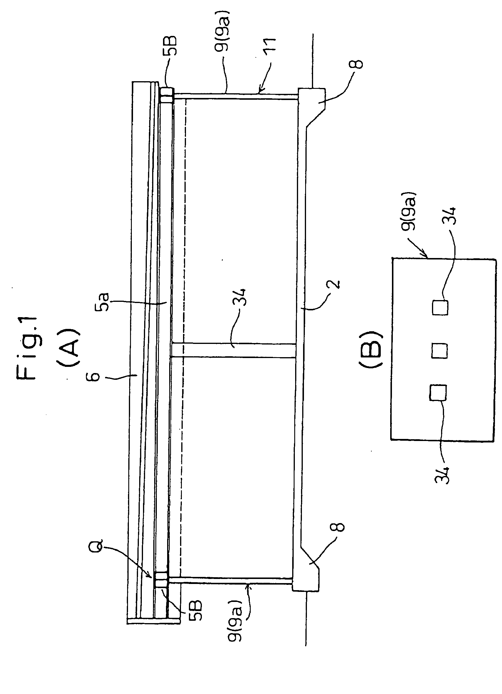
[0097] A first exemplary embodiment of the present invention is illustrated in FIGS. 1 to 4. FIG. 1 illustrates one example of a single-storied building of a size used for a convenience store or the like, constructed by the steel house (SH) method.

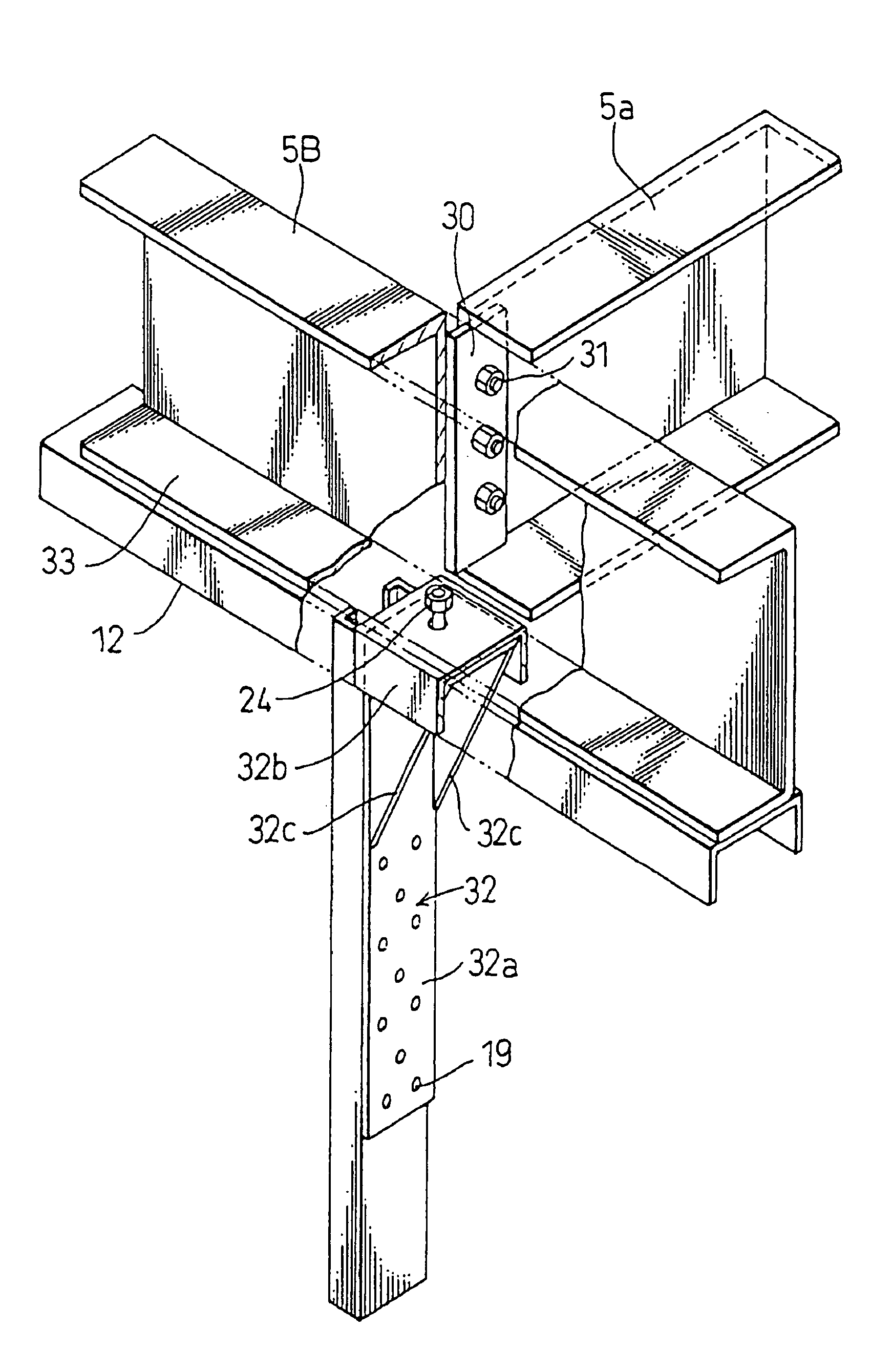
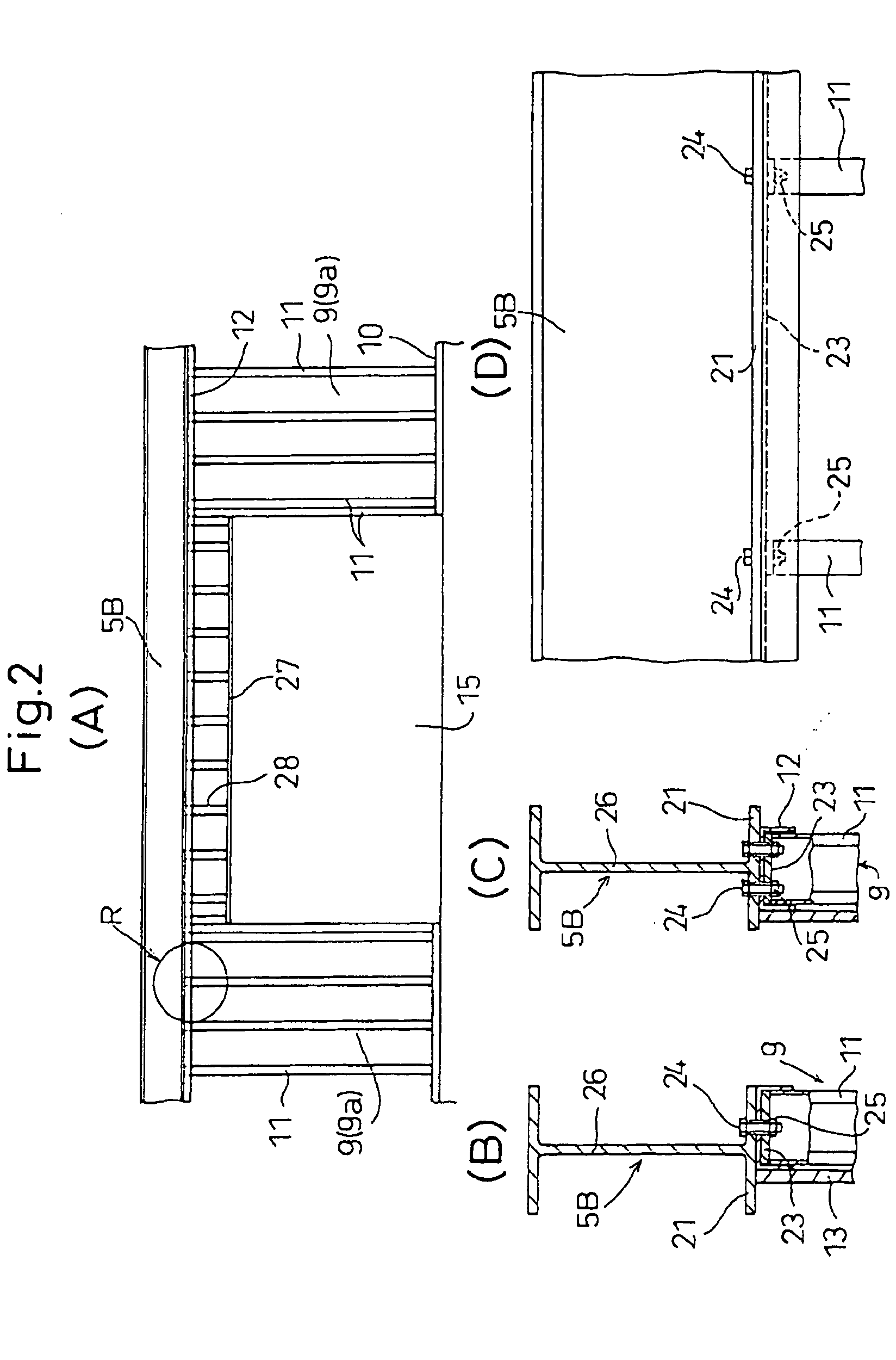
[0098] A continuous footing 8 and a floor (stall) 2 are formed by placing concrete, and wall frame panels 9 of thin light-gauge section steel are stood on the continuous footing 8. A structure of the wall frame panel 9 can be the same as shown in FIG. 21; i.e., the wall frame panel 9 is formed by standing vertical frame members 11 of thin light-gauge section steel on a lower frame member 10 of thin light-gauge section steel, placing an upper frame member 12 of thin light-gauge section steel on the vertical frame members 11, and fixing a construction s...


PUM


Abstract

A frame construction for a low rise building. In the construction, a wall frame panel is made of thin light-gauge section steel by bonding together a surface member, a lower frame member, vertical frame members and an upper frame member. Roof or floor support girders are made of heavyweight section steel having H-shape or channel shape. The girders are coupled to frame construction panels by bolts or hold-down fasteners.

Description

CROSS-REFERENCE TO RELATED APPLICATION(S) [0001] This application is a divisional of U.S. patent application Ser. No. 10 / 495,406 filed May 12, 2004 as a national phase application of International patent application No. PCT / JP02 / 04966 filed on May 22, 2002 (published as WO 03 / 031669) claiming priority to Japanese patent application Nos. JP 2001347119 and JP 2001348879 that were filed on Nov. 13, 2001 and Nov. 14, 2001, respectively. This application claims the benefit under 35 U.S.C. § 119 and § 235 of all of the aforementioned applications, all of which applications are incorporated by reference herein in their entireties.FIELD OF THE INVENTION [0002] The present invention relates to a frame construction for a low-rise building of one to three stories having a large opening such as a doorway or a window, and / or for a large span low-rise building of, e.g., one to three stories having a large opening such as a doorway or a window. BACKGROUND INFORMATION [0003] While a steel frame wor...

Claims


Application Information

Patent Timeline
IPC IPC(8): E04C3/02E04B5/18E04B1/08E04B1/24
CPCE04B1/08E04B2001/2415E04B2001/2496E04B2001/2457E04B2001/2463E04B2001/2448
Inventor HASHIMOTO, SHINICHIROMURAHASHI, YOSHIMITSUTOHNAI, SHIGEAKIEZAKI, TATSUOWATANABE, ATSUSHI
Owner NIPPON STEEL CORP
Why Eureka
Try Eureka