Electricity generating and air conditioning system with dehumidifier
Inactive Publication Date: 2006-02-23
LG ELECTRONICS INC
View PDF9 Cites 13 Cited by
Summary
Abstract
Description
Claims
Application Information
AI Technical Summary
This helps you quickly interpret patents by identifying the three key elements:
Problems solved by technology
Method used
Benefits of technology
Benefits of technology
[0007] The present invention has been made in view of the above-mentioned problems, and it is an object of the invention to provide an electricity generating and air conditioning system with a dehumidifier in which waste heat of an engine is recovered to be used as a heat source to dehumidify indoor air or to heat a refrigerant, so that the system exhibits a maximal enhancement in efficiency.
[0008] Another object of the invention is to provide an electricity generating and air conditioning system with a dehumidifier in which waste heat of an engine is recovered to be used as a heat source to dehumidify outdoor air blown to an outdoor heat exchanger, so that it is possible to prevent the outdoor heat exchanger from being frosted, and to achieve an enhancement in heating performance.
[0020] The electricity generating and air conditioning system according to the present invention has an advantage in that the waste heat of the engine is used to heat the refrigerant or to regenerate the indoor dehumidifying agent body, so that the system exhibits a high energy efficiency and enhances the pleasantness of a confined space to be air-conditioned.
[0021] The electricity generating and air conditioning system according to the present invention also has advantages in that the waste heat of the engine is used to prevent the outdoor heat exchanger from being frosted or is simply discharged to the atmosphere, so that the system exhibits a high heating performance and a high radiation performance.
[0022] In addition, the electricity generating and air conditioning system according to the present invention also has advantages in that the waste heat of the engine is used to prevent the outdoor heat exchanger from being frosted or to heat water, so that the system exhibits a high heating performance and a high energy efficiency.
Problems solved by technology
However, such a conventional electricity generating and air conditioning system has a problem in that waste heat of exhaust gas discharged from an engine and waste heat of cooling water used to cool the engine are inefficiently re-used, so that the system exhibits a low energy efficiency.
Method used
Image
Click on the blue label to locate the original text in one second.
Reading with bidirectional positioning of images and text.
Examples
second embodiment
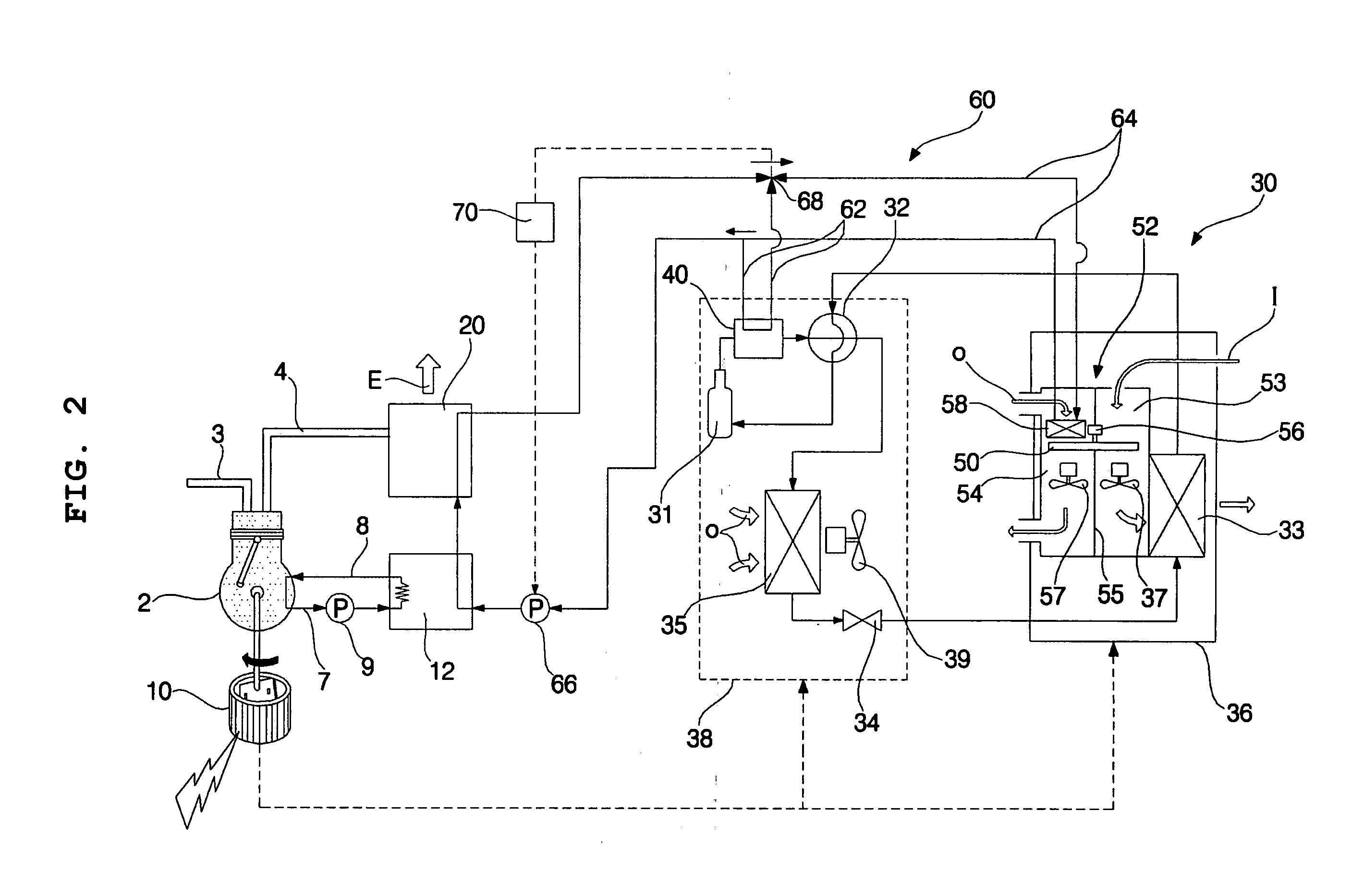
[0121] When the heat pump type air conditioner 30 operates in a heating mode, as shown in FIG. 5, the compressor 31 is driven by the electricity generated from the generator 10, as in the In this case, the directional valve 32 is switched to a heating mode, and the heat medium circulation pump 116 is driven. Also, the control valve 118 is switched to a heating mode, and the outdoor dehumidifier 82 operates.
[0122] The circulation of the refrigerant and heat medium according to the above-described driving and switching operations and the operation of preventing the outdoor heat exchanger 35 from being frosted are achieved in the same manner as in the second embodiment. Accordingly, no detailed description will be given.
[0123] On the other hand, when the heat pump type air conditioner 30 operates in a cooling mode, as shown in FIG. 6, the compressor 31 is driven by the electricity generated from the generator 10. In this case, the directional valve 32 is switched to a cooling mode, a...
fourth embodiment
[0152] The circulation of the refrigerant and heat medium according to the above-described switching operations to the heating mode and driving operations, and the enhancement in the heating performance of the indoor heat exchanger 33 and the effect of preventing the outdoor heat exchanger 35 from being frosted according to the refrigerant and heat medium circulation are achieved in the same manner as in the Accordingly, no detailed description will be given.
[0153] On the other hand, when the heat pump type air conditioner 30 operates in a cooling mode, the compressor 31 is driven by the electricity generated from the generator 10. In this case, the directional valve 32 is switched to a cooling mode, and the heat medium circulation pump 66 is driven. The control valve 38 is also switched to a cooling mode.
[0154] Also, the heat medium circulation pump 116 is driven, and the control valve 118 is switched to a cooling mode.
[0155] In accordance with the switching operations to the co...
first embodiment
[0168] Each of the indoor dehumidifiers 52, 52′ . . . is the same as the dehumidifier included in the electricity generating and air conditioning system according to the present invention, so that no detailed description thereof will be given.
[0169] Indoor regeneration heater circulation conduits 64, 64′ . . . , which are connected in parallel, guide a heat medium to respective indoor regeneration heaters 58, 58′ . . . of the indoor dehumidifiers 52, 52′.
[0170] The electricity generating and air conditioning system of this embodiment has the same configuration and functions as those of the fourth embodiment, except that the heat pump type air conditioner 30 includes a plurality of indoor units 36, 36′ . . . , a plurality of indoor dehumidifiers 52, 52′ . . . , and a plurality of indoor regeneration heater circulation conduits 64, 64′ . . . . Accordingly, the constituent elements of the seventh embodiment respectively corresponding to those of the fourth embodiment are designated by...
PUM
Abstract
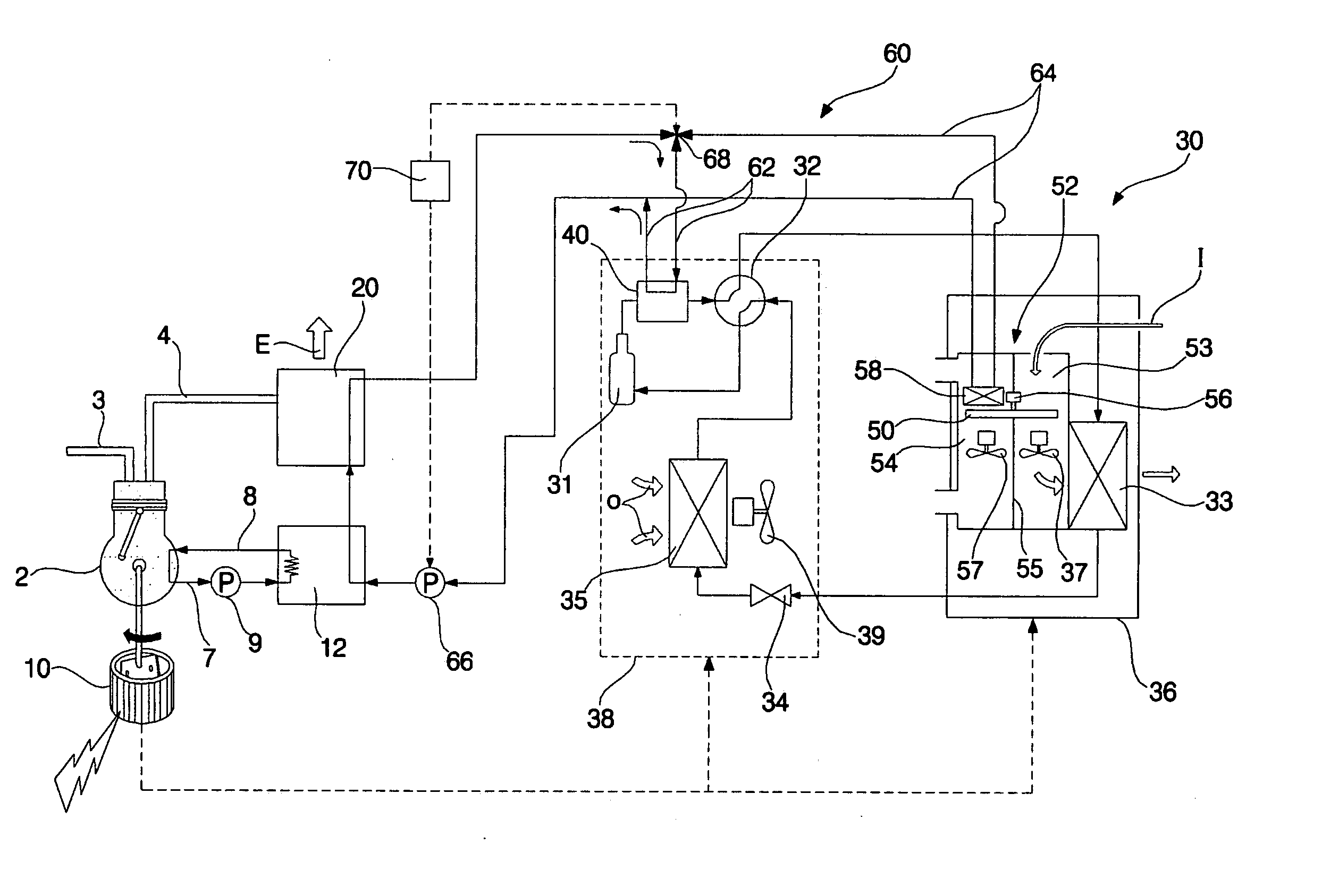
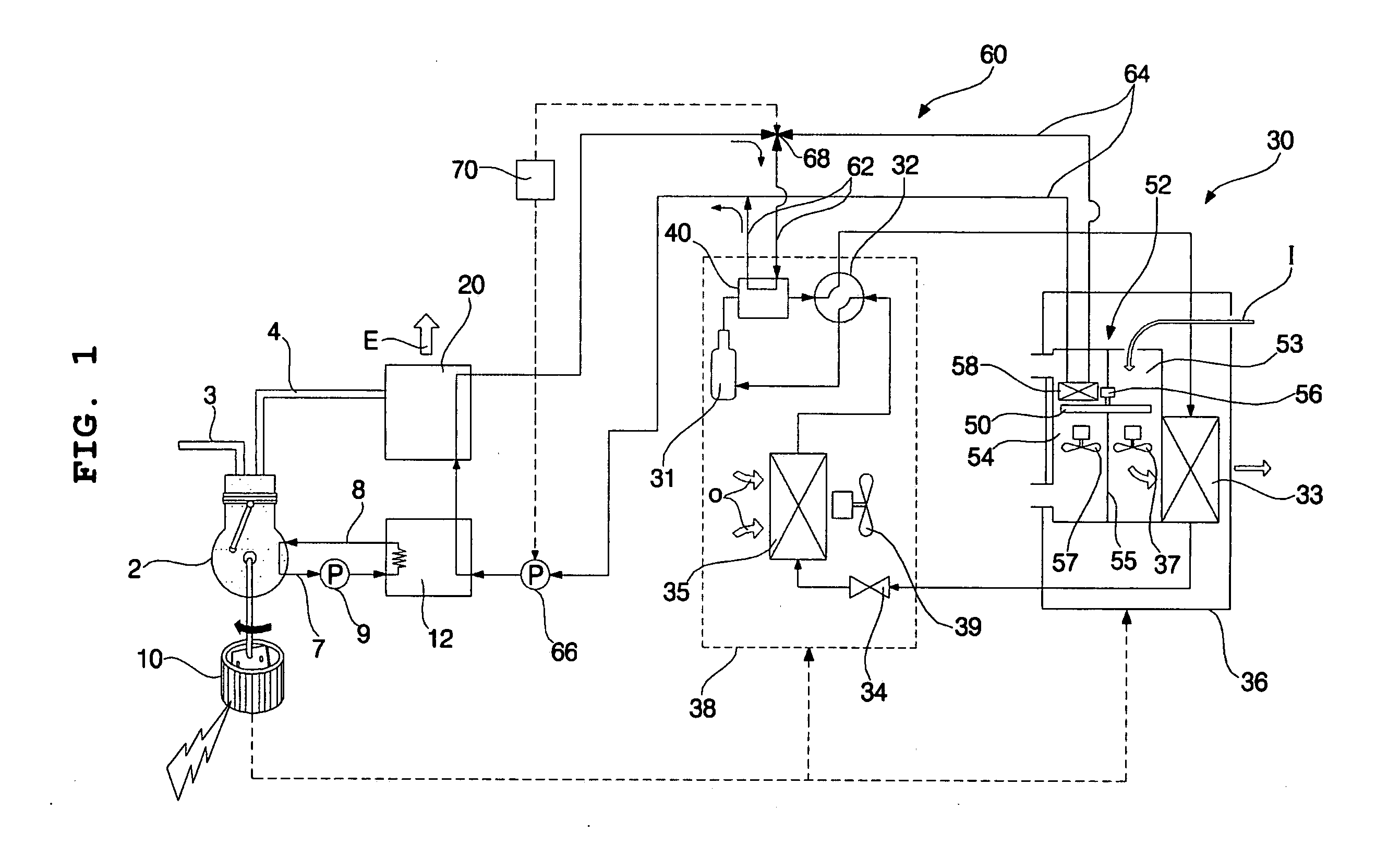
An electricity generating and air conditioningsystem with a dehumidifier. The system includes an engine, a generator connected to an output shaft of the engine to generate electricity, a heat pump type air conditioner, through which a refrigerant is circulated, the heat pump type air conditioner comprising a compressor, a directional valve, an outdoor heat exchanger, an expansion device, and an indoor heat exchanger, an indoor dehumidifying agent body to dehumidify indoor air, an indoor regeneration heater to regenerate the indoor dehumidifying agent body, and a waste heat recovering means to supply waste heat of the engine to the indoor regeneration heater, and thus, to allow the indoor regeneration heater to use the supplied waste heat as a heat source for the regeneration of the indoor dehumidifying agent body, or to supply the waste heat of the engine to the refrigerant of the heat pump type air conditioner, so that the system exhibits maximal efficiency.
Description
BACKGROUND OF THE INVENTION [0001] 1. Field of the Invention [0002] The present invention relates to an electricity generating and air conditioning system with a dehumidifier, and, more particularly, to an electricity generating and air conditioning system with a dehumidifier in which exhaust gas or cooling water of an engine is used to enhance the heating performance of an air conditioner or to dehumidify indoor air. [0003] 2. Description of the Related Art [0004] In general, electricity generating and air conditioning systems generate electricity by use of a rotating force outputted from an engine, and operate an air conditioner by use of the generated electricity. Such electricity generating and air conditioning systems are mainly used for multi-type air conditioners or large-scale air conditioners. [0005] Such electricity generating and air conditioning systems include an engine, a generator connected to an output shaft of the engine to generate electricity, and an air condition...
Claims
Application Information
Patent Timeline
Application Date:The date an application was filed.
Publication Date:The date a patent or application was officially published.
First Publication Date:The earliest publication date of a patent with the same application number.
Issue Date:Publication date of the patent grant document.
PCT Entry Date:The Entry date of PCT National Phase.
Estimated Expiry Date:The statutory expiry date of a patent right according to the Patent Law, and it is the longest term of protection that the patent right can achieve without the termination of the patent right due to other reasons(Term extension factor has been taken into account ).
Invalid Date:Actual expiry date is based on effective date or publication date of legal transaction data of invalid patent.

