Valve method for drilling with casing using pressurized drilling fluid

a valve and casing technology, applied in the field of casing drilling, can solve the problems of long time required for equalization of pressure, significant handling problems of large volume of fluid under pressure, and energy introduced, to compress the gas in the first place, and loss of energy

Active Publication Date: 2006-02-23
TESCO CORPORATION
View PDF14 Cites 38 Cited by
  • Summary
  • Abstract
  • Description
  • Claims
  • Application Information

AI Technical Summary

Benefits of technology

[0006] A valve, a drill string valve assembly and a method of drilling using compressed fluid as a drilling fluid has been invented. The valve and valve assembly may be used in order to prevent escape of compressed fluid during the time that a connection is being made into the drill string.

Problems solved by technology

If a compressible fluid such as, for example, air is used as a drilling fluid, significant handling problems can occur with this large volume of fluid under pressure.
Time required for the equalization of pressure would be long and at the same time energy introduced, to compress the gas in the first place, would be lost.

Method used


Image

  • Valve method for drilling with casing using pressurized drilling fluid
  • Valve method for drilling with casing using pressurized drilling fluid
  • Valve method for drilling with casing using pressurized drilling fluid

Examples


Embodiment Construction

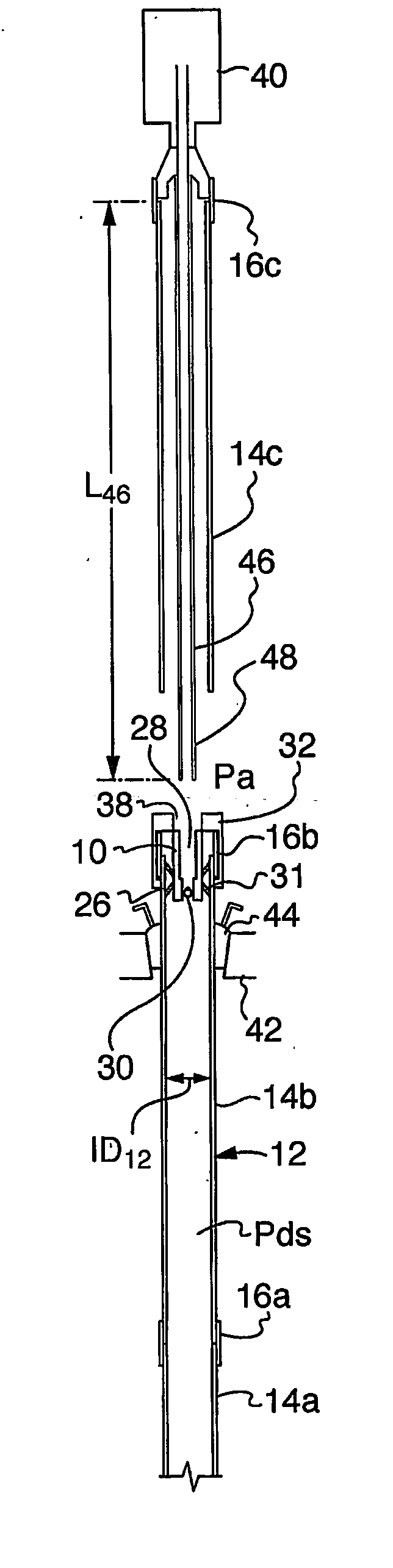
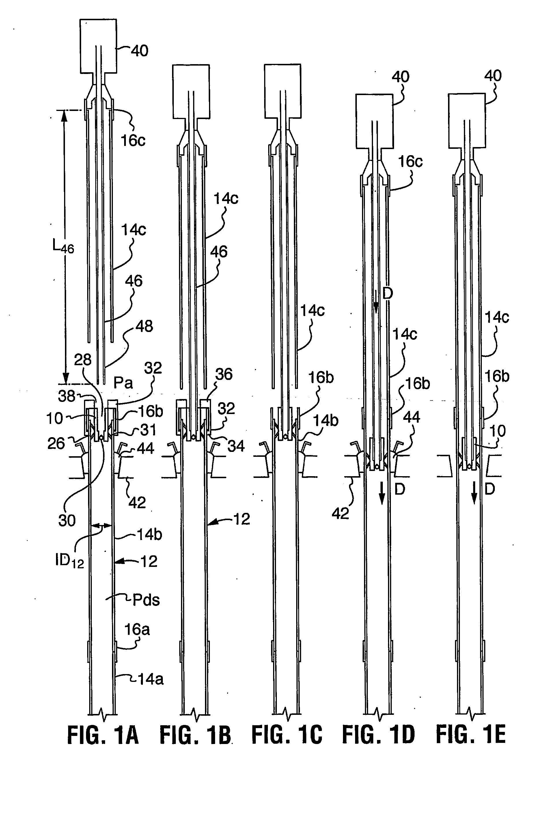
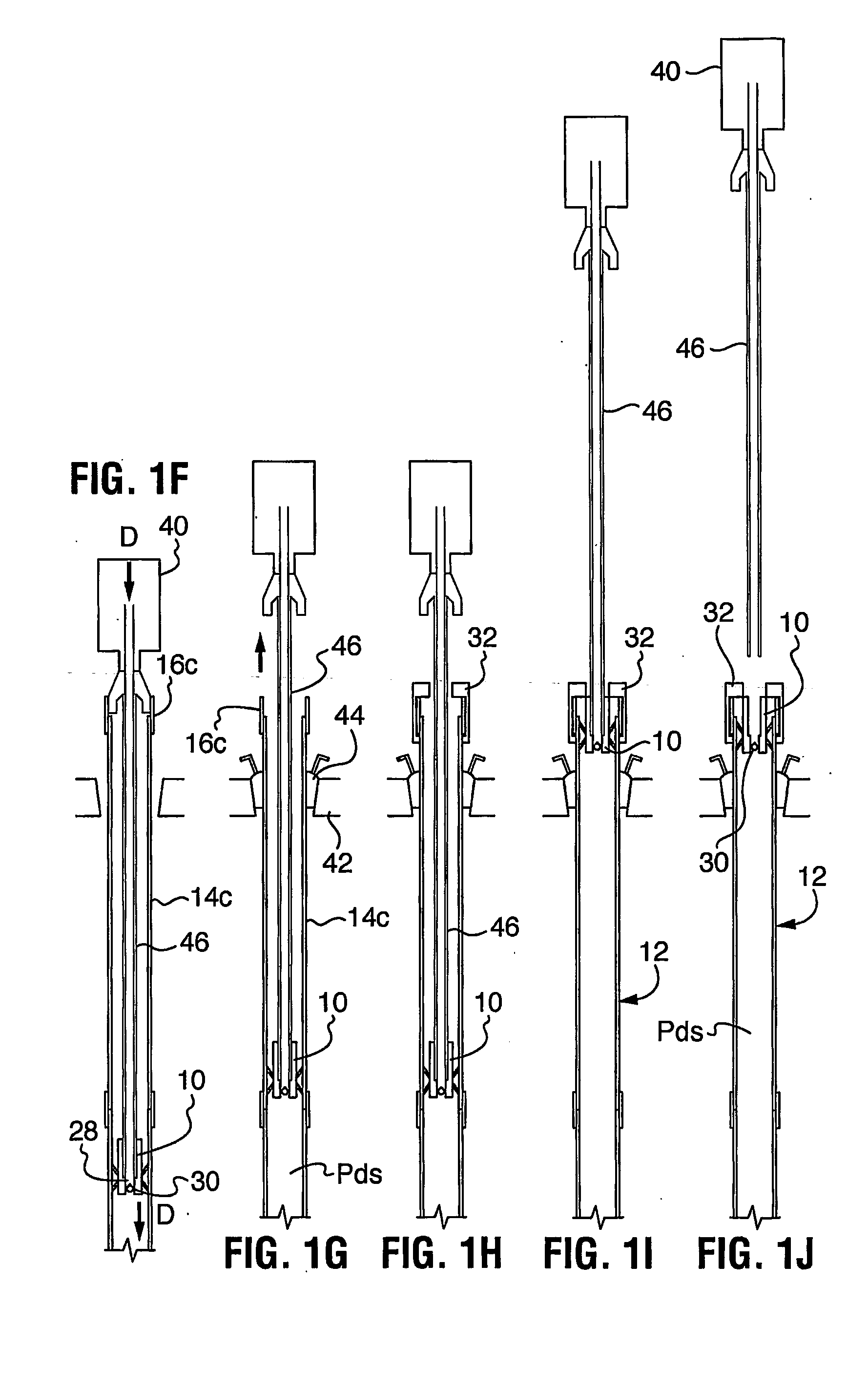
[0038] Referring to FIG. 1A, a valve device 10 according to the present invention is shown inserted into a drill string 12 inner diameter ID12. In the illustration, drill string 12 is being used for drilling with casing with compressed air as the drilling fluid and, as such, during drilling the pressure within drill string Pds is much greater than the atmospheric air pressure Pa. A top drive, indicated generally at 40, may be used to engage the drill string during drilling and to bring drill string tubulars for connection to the drill string. Of course, top drive 40 can be any drive mechanism that supports the axial load and applies rotational power to the top of the drill string. For example, top drive 40 could be replaced by a drive sub or a top drive with a casing clamp or casing drive assembly connected thereto. These options are encompassed herein by the term top drive.

[0039] Valve device 10 is positioned adjacent an upper end of the drill string and acts to seal against fluid...


PUM


Abstract

A valve (30), a drill string valve assembly (10) and a method of drilling using compressed fluid as a drill drilling fluid are described. The valve and valve assembly (10) may be used in order to prevent escape of compressed fluid during the time that a connection is being made into the drill string. The valve (10) can be insertable into a drill string inner diameter to seal against fluid passage past the body except through the valve (30) and can be selected to maintain fluid pressure in the drill string when the upper end of the drill string is open to atmosphere. The valve can also be capable of being releasably engaged to a drive mechanism, such as a top drive (40) which is handling the drill string (12) to be slidably moved within the drill string, as driven by the drive mechanism, but releasable from the drive mechanism, when the drive mechanism is removed from the drill string.

Description

FIELD [0001] This invention is directed to drilling with casing when using a pressurized fluid as a drilling fluid. BACKGROUND [0002] When drilling with casing, the volume of drilling fluid in the drill string is large. If a compressible fluid such as, for example, air is used as a drilling fluid, significant handling problems can occur with this large volume of fluid under pressure. [0003] When drilling, compressed gas has to be introduced through the ID of the top drive that is connected to the top end of the casing drill string. When the top drive is required to pick up a next joint of casing, the top drive is removed from the casing string ID. During that time if the drill string is left open, compressed gas can exit under considerable pressure, which would prevent a connection from being made until the pressure in the casing drill string is equalized with the atmospheric pressure. Time required for the equalization of pressure would be long and at the same time energy introduce...

Claims


Application Information

Patent Timeline
Patent Type & Authority Applications(United States)
IPC IPC(8): E21B21/10E21B7/20
CPCE21B21/10E21B7/20
Inventor WALTER, BRUNOHTESSARI, ROBERTMANGMAN, PERG
Owner TESCO CORPORATION
Why Eureka
Try Eureka