Anodic oxide film and anodizing method

an anodizing method and anodizing technology, applied in the field anodizing method, can solve the problems of difficult to have uniform growth uneven thickness of film, and rust in the pores, etc., to achieve easy formation of anodizing oxide film, high impact resistance, and corrosion resistance.

Active Publication Date: 2006-02-23
SUZUKI MOTOR CORP
View PDF5 Cites 29 Cited by
  • Summary
  • Abstract
  • Description
  • Claims
  • Application Information

AI Technical Summary

Benefits of technology

[0025] According to the present invention, the anodic oxide film formed has a corrosion resistance which is equal to or superior to the conventional film formed by sealing the pores after anodization. It is effective for use under highly corrosive conditions. Preferably, an anodic oxide film having high impact resistance can be obtained. The anodizing method of the present invention can facilitate the formation of an anodic oxide film having such properties at a low cost so that it is industrially very useful.

Problems solved by technology

Accordingly, water which will be a cause for rust tends to invade into the pores.
When a groove or like of the first piston ring of an engine is anodized for improving its abrasion resistance, it is difficult to have uniform growth of an anodic oxide film because aluminum or aluminum alloy used for the piston or the like has been segregated owing to a large silicon content (8% by weight or greater but not greater than 30% by weight).
As a result, the film thickness is not uniform and varies widely.
Consequently, it is difficult for the anodic oxide to grow.
This method, however, requires the re-melting step in addition to the anodizing step and may be accompanied with another problem such as thermal strain.
Since this method requires, in addition to the anodizing step, a roller-burnishing step, it cannot be applied to minute places such as a groove of a piston ring which may be broken by roller-burnishing.
In the prior art, however, the growth of an anodic oxide film is disturbed around silicon and it is therefore difficult to form an anodic oxide film while the mother material comprises silicon.
However, the method requires a re-melting step in addition to the anodizing step and may therefore be accompanied with the problem such as thermal strain.
Then, a longer anodization period is required to obtain a film having a desired thickness so that difficulty is encountered in reducing anodization time.

Method used


Image

  • Anodic oxide film and anodizing method
  • Anodic oxide film and anodizing method
  • Anodic oxide film and anodizing method

Examples


Embodiment Construction

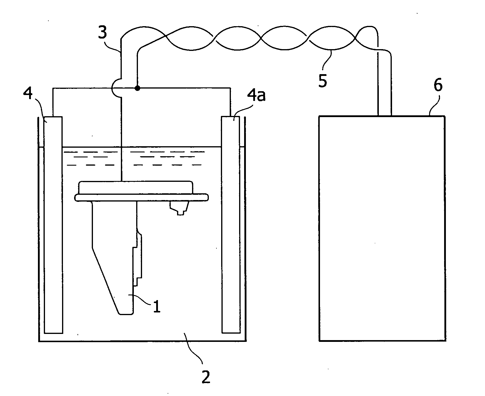
[0043] The present invention now will be described more fully hereinafter in which embodiments of the invention are provided with reference to the accompanying drawings. This invention may, however, be embodied in many different forms and should not be construed as limited to the embodiments set forth herein; rather, these embodiments are provided so that this disclosure will be thorough and complete, and will fully convey the scope of the invention to those skilled in the art.

[0044] The terminology used in the description of the invention herein is for the purpose of describing particular embodiments only and is not intended to be limiting of the invention. As used in the description of the invention and the appended claims, the singular forms “a”, “an” and “the” are intended to include the plural forms as well, unless the context clearly indicates otherwise.

[0045] Unless otherwise defined, all technical and scientific terms used herein have the same meaning as commonly understoo...


PUM

PropertyMeasurementUnit
frequencyaaaaaaaaaa
frequencyaaaaaaaaaa
frequencyaaaaaaaaaa

Abstract

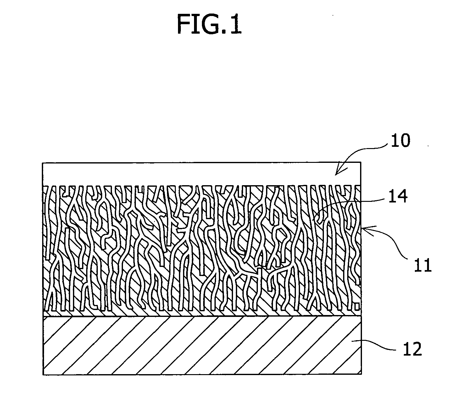
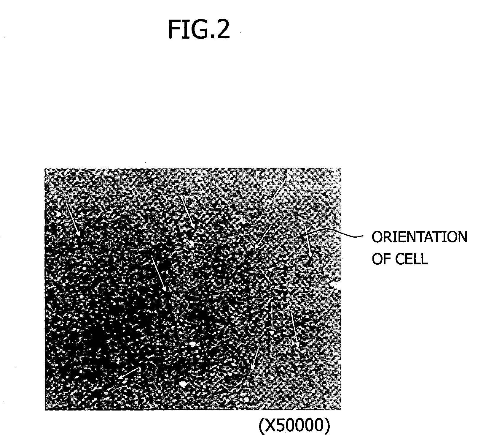
An object of the present invention is to obtain an aluminum or aluminum alloy member having a uniform and dense anodic oxide film having sufficient corrosion and impact resistances. Provided is an anodic oxide film which has been formed on the surface of aluminum or aluminum alloy, the film comprising cells which have grown in random directions relative to the surface of the aluminum or aluminum alloy and thus have no orientation.

Description

RELATED APPLICATION [0001] This application claims priority from Japanese Patent Application No. 2004-240763, filed Aug. 20, 2004, the disclosure of which is incorporated by reference herein in its entirety. BACKGROUND OF THE INVENTION [0002] 1. Field of the Invention [0003] The present invention relates to an anodic oxide (alumite) film formed on the surface of aluminum or aluminum alloy and an anodizing method for obtaining such a film. In particular, the present invention relates to an anodic oxide film with excellent corrosion resistance and uniform film thickness and an anodizing method for obtaining such a film. [0004] 2. Description of the Related Art [0005] Members having an anodic oxide film formed on the surface of aluminum or aluminum alloy have been used conventionally for automotive parts and the like used under a corrosive condition. Aluminum parts such as outboard motors which require high corrosion resistance have to be subjected to a rust-preventive treatment after ...

Claims


Application Information

Patent Timeline
Patent Type & Authority Applications(United States)
IPC IPC(8): C25D11/04
CPCC25D11/024C25D11/04
Inventor YAMAMOTO, TOMOHARUTANAKA, HIROOMI
Owner SUZUKI MOTOR CORP
Why Eureka
Try Eureka