Cassette type radiographic apparatus

Active Publication Date: 2006-02-23
CANON KK
View PDF7 Cites 27 Cited by
  • Summary
  • Abstract
  • Description
  • Claims
  • Application Information

AI Technical Summary

Benefits of technology

[0013] The present invention has been made in view of the above problems, and ha

Problems solved by technology

In the conventional cassette type radiographic apparatus which uses the FPD, problems occur when a columnar crystal phosphor such as CsI (cesium iodide crystal) is used in place of the particle phosphor 131.
As the columnar crystal phosphor is more vulnerable to the external force, the conventional technique for protecting the photoelectrical conversion devices cannot sufficiently protect the columnar crystal phosphor.
When this apparatus is used as a portable cassette type radiographic apparatus, problems occur.
In the cassette type radiographic apparatus, however, the radiographic target is often a body portion, e.g., a limb, which does produce many scattered rays, and accordingly a scattered ray removing mechanism (grid) is not usually mounted due

Method used


Image

  • Cassette type radiographic apparatus
  • Cassette type radiographic apparatus
  • Cassette type radiographic apparatus

Examples


first embodiment

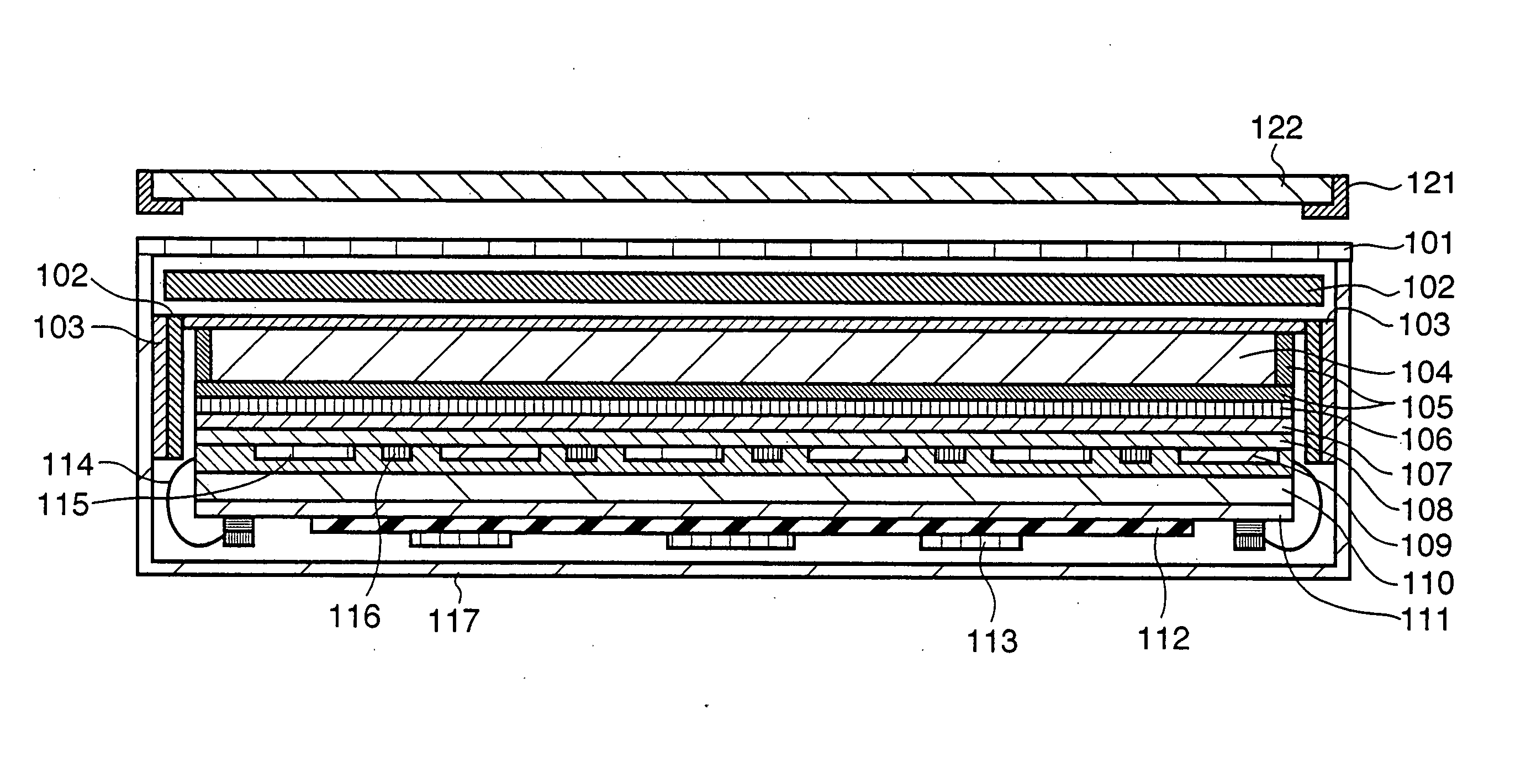
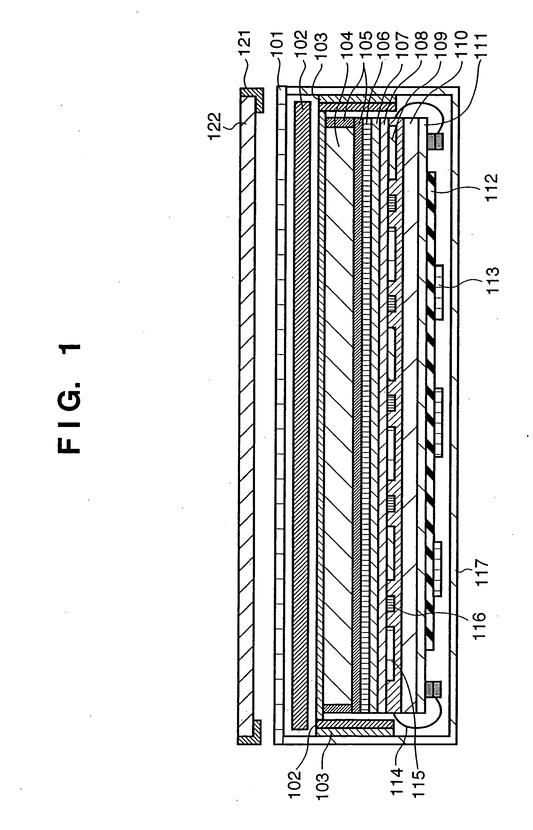
[0037] The first preferred embodiment of the present invention will be described in detail. FIG. 1 is a sectional view of a cassette type radiographic apparatus which uses a columnar crystal phosphor according to the first embodiment of the present invention. The cassette type radiographic apparatus of the first embodiment includes a columnar crystal phosphor 104 which converts X-rays into visible light, a photodetector including photoelectric conversion devices 109 which convert the visible light converted by the columnar crystal phosphor 104 into electrical signals, and a case which houses the columnar crystal phosphor 104 and photoelectric conversion devices 109. The case includes a case lid 101 which has an X-ray incident surface and a case main body 117 which supports the case lid 101. A buffer member 102 which buffers a force from outside the case and a highly rigid member 103 which is more rigid than the columnar crystal phosphor 104 are arranged between the case and the colu...

second embodiment

[0083] The second preferred embodiment of the present invention will be described with reference to FIG. 2.

[0084] According to the first embodiment, after the columnar crystal phosphor (CsI) 104 is deposited on the highly rigid member 103, the columnar crystal phosphor (CsI) 104 is adhered to the photoelectric conversion devices 109 by using the adhesion layer 106. In contrast to this, according to the second embodiment, a columnar crystal phosphor (CsI) 104 is directly deposited on photoelectric conversion devices 109 through second and first protection layers 107 and 108.

[0085] In FIG. 2, to protect the columnar crystal phosphor 104 directly deposited on the photoelectric conversion devices 109, a highly-rigid member 103 is placed above the columnar crystal phosphor 104, so that the columnar crystal phosphor 104 is protected from an external pressure.

[0086] The first and second embodiments are different from each other in formation of the phosphor. When an indirect X-ray area s...

third embodiment

[0090] The third preferred embodiment of the present invention will be described with reference to FIG. 3.

[0091] The third embodiment is different from the first embodiment in two respects. According to the first difference, a highly rigid member 103 is not arranged on the side of a columnar crystal phosphor 104. As the side surfaces of the columnar crystal phosphor 104 have short sides, an external force does not act on the side surfaces often. In packaging a cassette type radiographic apparatus, there is a demand for a smaller weight. In view of the above facts, an impact from the side surface is not considered in the design. According to the second difference, the highly rigid member 103 is placed above a deposition substrate plate 118. Of the specifications required for a highly rigid member, the specification that the heat resistance and thermal expansion coefficient should be almost equal to those of glass is not satisfied. Thus, when, e.g., a material which is more appropria...


PUM


Abstract

A radiographic apparatus includes a columnar crystal phosphor which converts X-rays into visible light, a photodetector which converts the visible light into an electrical signal, and a case (a case lid and case main body) which houses the columnar crystal phosphor and photodetector. A buffer member which buffers a force from outside the case (the case lid and case main body) and a highly rigid member which has higher rigidity than that of the columnar crystal phosphor are arranged between the case (the case lid and case main body) and columnar crystal phosphor.

Description

FIELD OF THE INVENTION [0001] The present invention relates to a cassette type radiographic apparatus which uses a columnar crystal phosphor. BACKGROUND OF THE INVENTION [0002] With a conventional radiographic apparatus, an X-ray source projects X-rays to an object (e.g., a medical patient). X-ray beams transmitted through the object are detected to radiograph the object by a screen film cassette, film autochanger, CR (Computed Radiography), FPD (Flat Panel Detector), or the like. [0003] In the field of radiography, a high-resolution solid X-ray detector which uses an FPD is proposed. This solid X-ray detector has an X-ray sensor including a two-dimensional array in which arrays of 3,000 to 4,000 photoelectric conversion devices (e.g., photodiodes) are arrayed two-dimensionally. Each photoelectric conversion device generates an electrical signal corresponding to the X-ray dose projected to the X-ray sensor. The X-ray image of an object is obtained by arranging the object between an ...

Claims


Application Information

Patent Timeline
IPC IPC(8): G01T1/20
CPCG01T1/2018G01T1/2006
Inventor HAYASHIDA, SHINSUKE
Owner CANON KK
Why Eureka
Try Eureka