Seal ring

a technology of sealing rings and sidewalls, applied in the field of sealing rings, can solve the problems of easy vomitation, and achieve the effect of preventing the wear of the sidewall surfa

Active Publication Date: 2006-02-23
NOK CORP
View PDF22 Cites 17 Cited by
  • Summary
  • Abstract
  • Description
  • Claims
  • Application Information

AI Technical Summary

Benefits of technology

[0052] Accordingly, even if the foreign matter existing in the sealed fluid has entered the separation portion, it is not bitten in the separation portion, and it is permitted to prevent the wear of the fitting surfaces from occurring. It is also permitted to prevent the wear of the sidewall surface from occurring due to the fact that the foreign matter is bitten into the separation portion.

Problems solved by technology

Besides, even if any foreign matter has entered the sliding part, it can be easily vomited.

Method used


Image

  • Seal ring
  • Seal ring
  • Seal ring

Examples


first embodiment

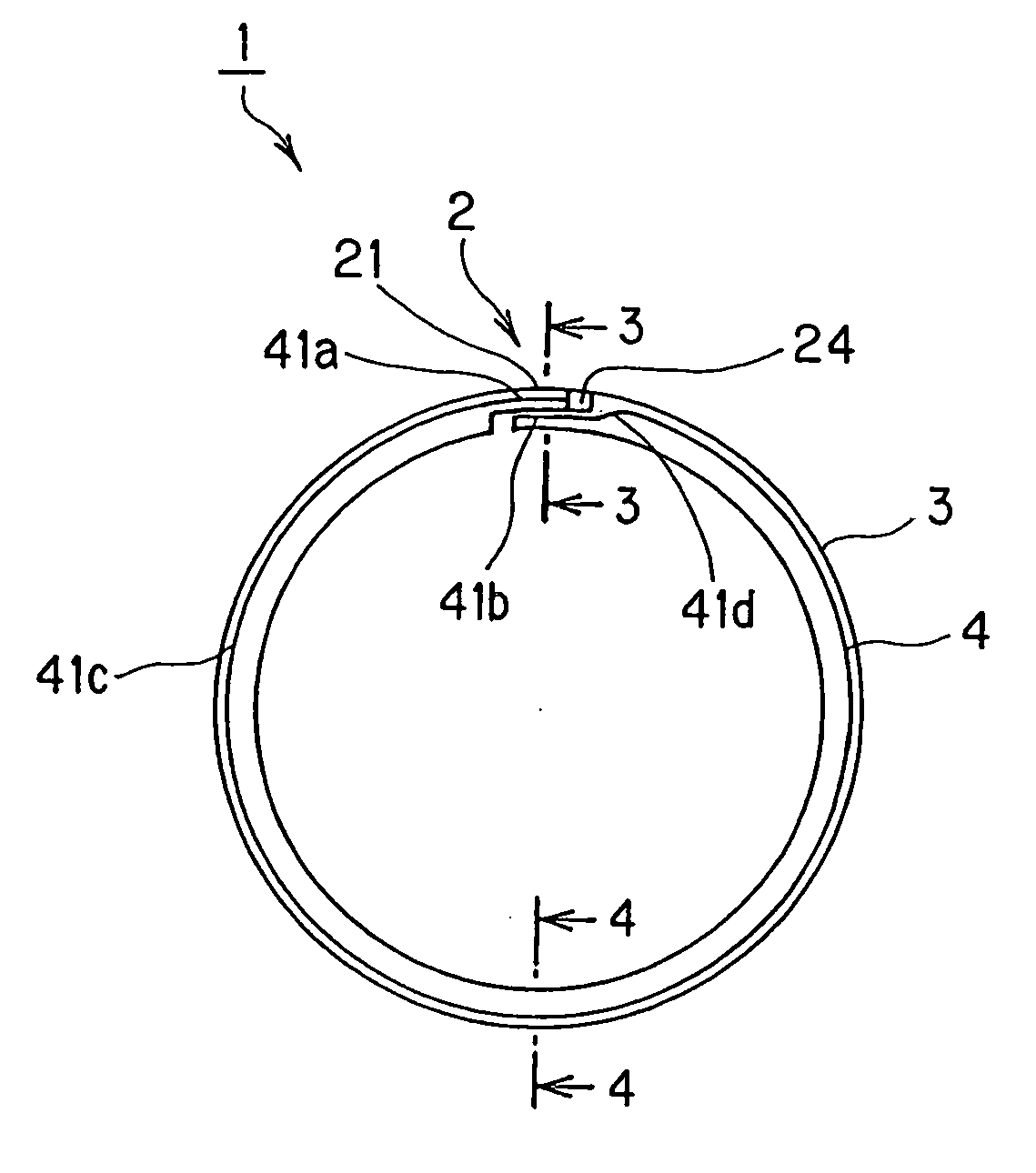
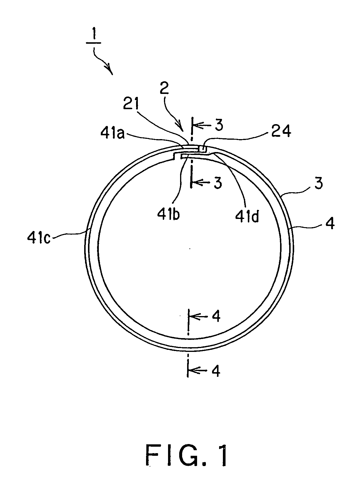
[0103] A seal ring 1 according to the first embodiment of the present invention will be described with reference to FIG. 1-FIG. 5. FIG. 1 is a plan view of the seal ring 1 according to the first embodiment of the invention, FIG. 2 is a perspective view, partly broken away, showing the mounted state of the seal ring 1 according to this embodiment, FIG. 3 is a sectional view of the seal ring 1 taken along 3-3 indicated in FIG. 1, FIG. 4 is a sectional view of the seal ring 1 taken along 4-4 indicated in FIG. 1, and FIG. 5 is an enlarged view of a part C in FIG. 4.

[0104] The seal ring 1 serves to seal the annular interspace between a shaft 70 which is one member inserted in a shaft hole and a housing 80 which is the other member provided with the shaft hole, and it is used in a state where it is mounted within an annular groove 71 provided in the shaft 70.

[0105] Besides, the seal ring 1 is formed of a resin material, and it includes a first seal portion 4 for sealing the sidewall sur...

second embodiment

[0148] A seal ring 1B according to the second embodiment of the present invention will be described with reference to FIG. 9-FIG.

[0149] 12. FIG. 9 is a perspective view, partly broken away, showing the mounted state of the seal ring 1B according to this embodiment, FIG. 10 is a sectional view of a separation portion (corresponding to the section 3-3 of the seal ring 1 shown in FIG. 1), FIG. 11 is a sectional view corresponding to the section 4-4 of the seal ring shown in FIG. 1, and FIG. 12 is an enlarged view of a part H in FIG. 11.

[0150] As compared with the seal ring 1 according to the first embodiment, this embodiment consists in that the sectional shape of the seal ring is made substantially rectangular, and that the side surface of substantially rectangular section on the unsealed fluid side A is provided with linear contact portions which come into linear contact with the sidewall surface 72 of an annular groove 71. Incidentally, identical numerals and signs are assigned to...

example 1

[0164] A more practicable example will be described on the seal ring according to the first embodiment.

[0165] First, as a Comparative Example 1, there was used the seal ring 100 of substantially rectangular section fabricated by injection molding with polyether etherketone (PEEK) in which several sorts of fillers were compounded (seal ring shown in FIGS. 34 and 35 as explained in the paragraph of the prior art).

[0166] Besides, in this example, the seal ring 100 molded as the Comparative Example 1 was additionally worked to obtain the seal ring 1 shown in FIGS. 1-5 in the first embodiment.

[0167] Here, the dimensions of the individual parts of the seal ring 1 were set at seal-ring outside diameter=47.85 mm, seal-ring wall thickness 1.9 mm, seal-ring height 2 mm, 1=0.6 mm, θ1=about 15 degrees, θ2=about 15 degrees, b=0.25 mm, c=0.25 mm, and ls=0.2 mm.

[0168] Besides, as a Comparative Example 2, there was used a seal ring 400 fabricated by additionally working the seal ring 100 molded...


PUM


Abstract

A seal ring which maintains a stable sealing performance over a long term is provided. In a first seal portion 4, linear contact portions which come into linear contact with the sidewall surface of an annular groove on the unsealed fluid side are continuously extended over the whole circumference of the seal ring from one side of a separation portion 2 to the other side thereof, and the linear contact part provided at the convex part 21 of the separation portion 2, and the linear contact part provided at the concave part 24 of the separation portion 2 are located at a distance in the diametric direction of the seal ring.

Description

TECHNICAL FIELD [0001] This invention relates to a seal ring for sealing the annular interspace between two members which are disposed so as to be rotatable relative to each other. BACKGROUND ART [0002] Heretofore, a seal ring of this type has been employed in hydraulic devices, for example, the automatic transmission of an automobile. [0003] Now, a seal ring according to a prior-art technique will be explained with reference to FIGS. 34 and 35. [0004]FIG. 34 is a planar model view of the seal ring according to the prior-art technique, while FIG. 35 is a model-like sectional view showing the mounted state of the seal ring according to the prior-art technique. [0005] The illustrated seal ring 100 serves to seal the annular interspace between a housing 200 provided with a shaft hole and a shaft 300 inserted in the shaft hole, and it is used in a state where it is mounted within an annular groove 301 provided in the shaft 300. [0006] The seal ring 100 is formed of a resin material, and...

Claims


Application Information

Patent Timeline
Patent Type & Authority Applications(United States)
IPC IPC(8): B60T11/236F16J9/14F16J9/20F16J15/3272F16J15/44
CPCF16J15/441F16J9/14F16J15/3272F16J15/32F16J9/20F16J15/18
Inventor NAKAOKA, SHINYAEGUCHI, NOBUYUKIJOTAKI, NAOHIROYASUDOMI, TAKAAKI
Owner NOK CORP
Why Eureka
Try Eureka