Vehicular power line communication system

a technology of communication system and power line, which is applied in the direction of electrical devices, process and machine control, frequency-division multiplex, etc., can solve the problems of inpractical configuration and increase the cost of the apparatus, and achieve the effect of facilitating the cabling of the +b line and improving workability

Inactive Publication Date: 2006-02-23
YAZAKI CORP
View PDF6 Cites 26 Cited by
  • Summary
  • Abstract
  • Description
  • Claims
  • Application Information

AI Technical Summary

Benefits of technology

[0026] With the above-described configuration, the ground line constituting the power line coupling the front communication area provided on the front side of the vehicle and the rear communication area provided

Problems solved by technology

However, if such a configuration is adopted, then it is necessary to add the element, and an apparatus scal

Method used


Image

  • Vehicular power line communication system
  • Vehicular power line communication system
  • Vehicular power line communication system

Examples


first embodiment

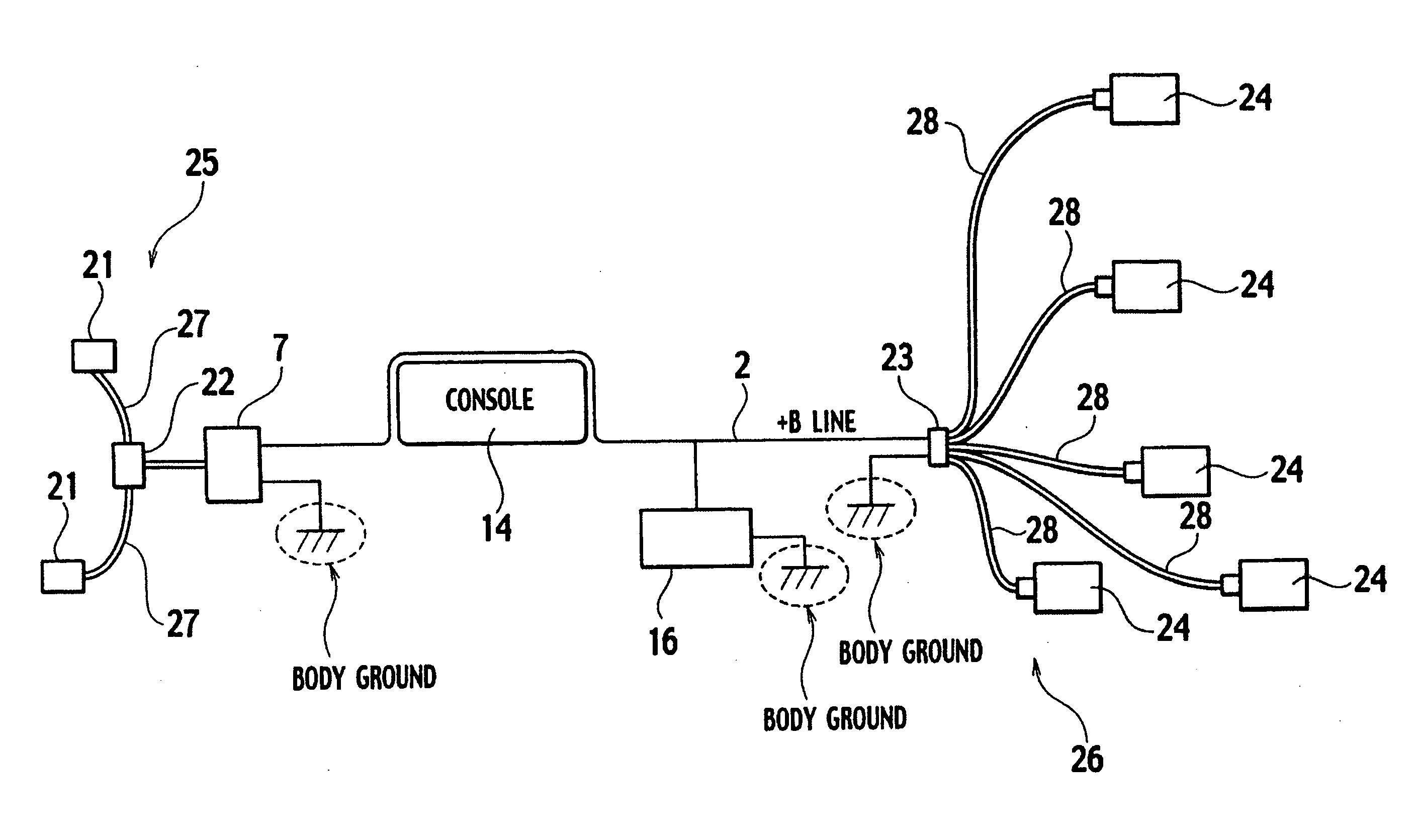
[0049] The first embodiment of the present invention is described below. FIG. 7 is an explanatory view of the case of coupling an in-door communication area 3 disposed in a door 5 mounted on the vehicle and an in-power-seat communication area 4 disposed in a seat 6 mounted on the vehicle to each other by using the power line 2.

[0050] In the in-door communication area 3, there are arranged a junction connector 8 and the respective ECUs 10 branched from the junction connector 8 and connected to one another, such as an ECU for controlling a power window, an ECU for controlling a door mirror and an ECU for a door lock. A power supply voltage outputted from a battery 16 is supplied to the respective ECUs 10 through the power line 2 and branch power lines 12. Moreover, communication data among the respective ECUs 10 is superposed on the respective branch power lines 12, and data transmission is thus performed.

[0051] Meanwhile, in the in-power-seat communication area 4, there are arrange...

second embodiment

[0059] Next, the second embodiment of the present invention is described below. In the above-described first embodiment, description has been made of the case of using the wire as the GND line of the power line 2. In the second embodiment, description is made of the case of using a metal portion 15 (for example, a body) constituting a vehicle body as a ground, that is, the GND line without using the wire. Basically, a principle in the second embodiment is similar to the principle described with reference to FIGS. 5A to 6C.

[0060]FIGS. 9A and 9B are explanatory views showing the power line 2 cabled between the PLC apparatuses 1a and 1b provided in the communication areas different from each other: FIG. 9A shows a connecting state of the power line 2; and FIG. 9B shows an equivalent circuit thereto. As shown in FIG. 9A, the GND line is set as the vehicle body metal portion 15 such as the body of the vehicle. Moreover, as shown in FIG. 9B, the power line 2 has impedance with characteri...


PUM


Abstract

Plural communication areas are provided, and plural electronic control units for mutually making communication in each of the communication areas are provided. A vehicular power line communication system includes a power line coupling the respective communication areas to one another, branch power lines coupling the respective electronic control units in each of the communication areas to one another, and a battery for supplying electric power to the electronic control units through the power line and the branch power lines. The power line is formed of a +B line turning to a positive polarity and a ground line turning to a negative polarity, which are cabled to be spaced from each other in a part of the power line. The branch power lines superpose communication data thereon, thereby making data communication.

Description

BACKGROUND OF THE INVENTION [0001] 1. Field of the Invention [0002] The present invention relates to a vehicular power line communication system for superposing communication data among respective electronic control units (ECUs) on power lines for supplying electric power to respective instruments mounted on a vehicle, thereby making communication. [0003] 2. Description of the Related Art [0004] In a vehicle in recent years, a power line communication system has been proposed in order to make data communication among various ECUs, for example, as disclosed in Japanese Patent Laid-Open Publication No. 2004-56197. [0005] The power line communication system superposes communication data among ECUs mounted on the vehicle on power lines cabled in order to supply electric power to the respective ECUs, thus making it possible to reduce the number of harnesses connecting the respective ECUs to one another. [0006]FIG. 1 is a block diagram showing a configuration of an ECU connected to the po...

Claims


Application Information

Patent Timeline
IPC IPC(8): H04B3/54B60L1/00G05B11/01H04L69/40
CPCH04B3/548H04B3/56H04L25/0266H04B2203/5491H04B2203/547
Inventor YANAGIDA, YOSHIRAISHI, NAOYUKIKAWAMURA, ATSUSHISUGIMOTO, TERUMITSU
Owner YAZAKI CORP
Why Eureka
Try Eureka