Supercharge Your Innovation With Domain-Expert AI Agents!

Clock signal distribution utilizing differential sinusoidal signal pair

a timing and signal technology, applied in the direction of generating/distributing signals, pulse techniques, instruments, etc., can solve the problems of power consumption and energy consumption, and achieve the effect of promoting energy efficiency and power consumption

Inactive Publication Date: 2006-02-23
GLOBALFOUNDRIES INC
View PDF13 Cites 0 Cited by
  • Summary
  • Abstract
  • Description
  • Claims
  • Application Information

AI Technical Summary

Benefits of technology

The invention provides a method for generating a clock signal on an IC using a differential sinusoidal signal pair. This method allows for the efficient use of low-swing signals, reduces power consumption, and improves energy efficiency. Additionally, the invention includes a method for distributing the clock signal on the IC using a differential basis, which filters out noise and concentrates energy at the clock frequency. These technical effects make the invention useful in a variety of applications.

Problems solved by technology

Since a differential sinusoidal signal pair is used for distributing the clock signal, very low-swing signals may be employed, thereby greatly economizing on power consumption.

Method used


Image

  • Clock signal distribution utilizing differential sinusoidal signal pair
  • Clock signal distribution utilizing differential sinusoidal signal pair
  • Clock signal distribution utilizing differential sinusoidal signal pair

Examples


Embodiment Construction

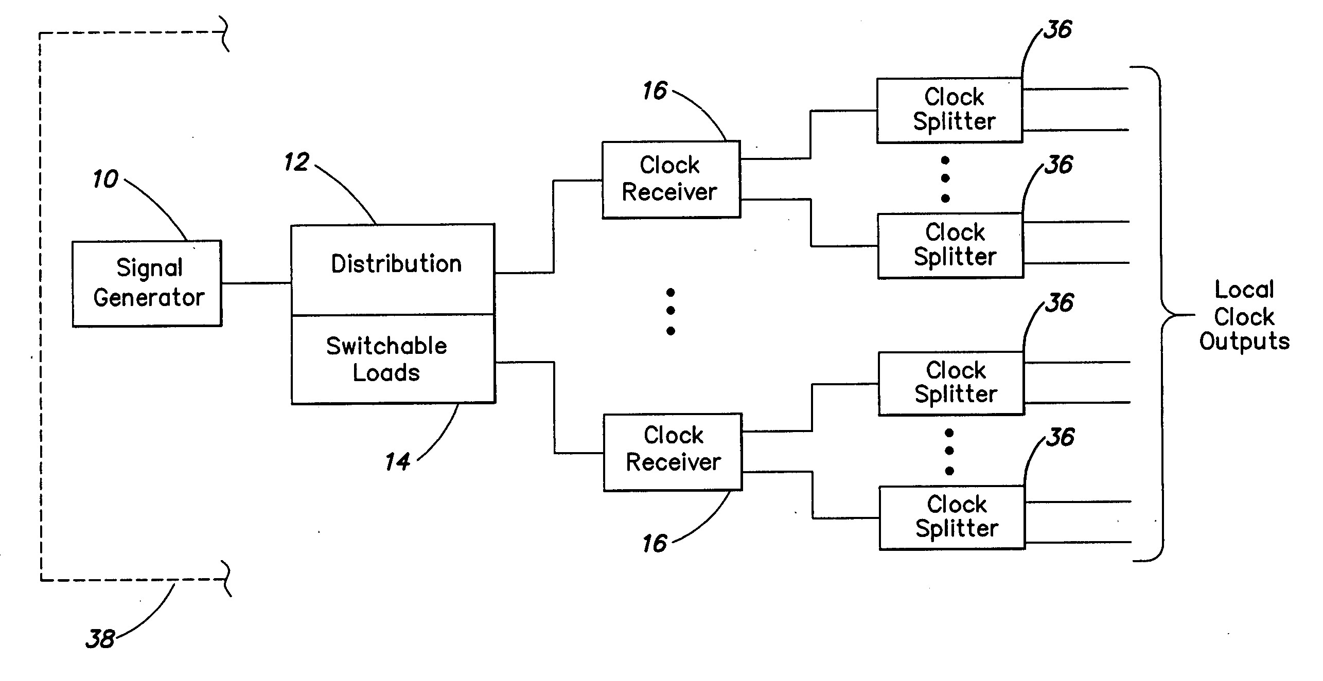
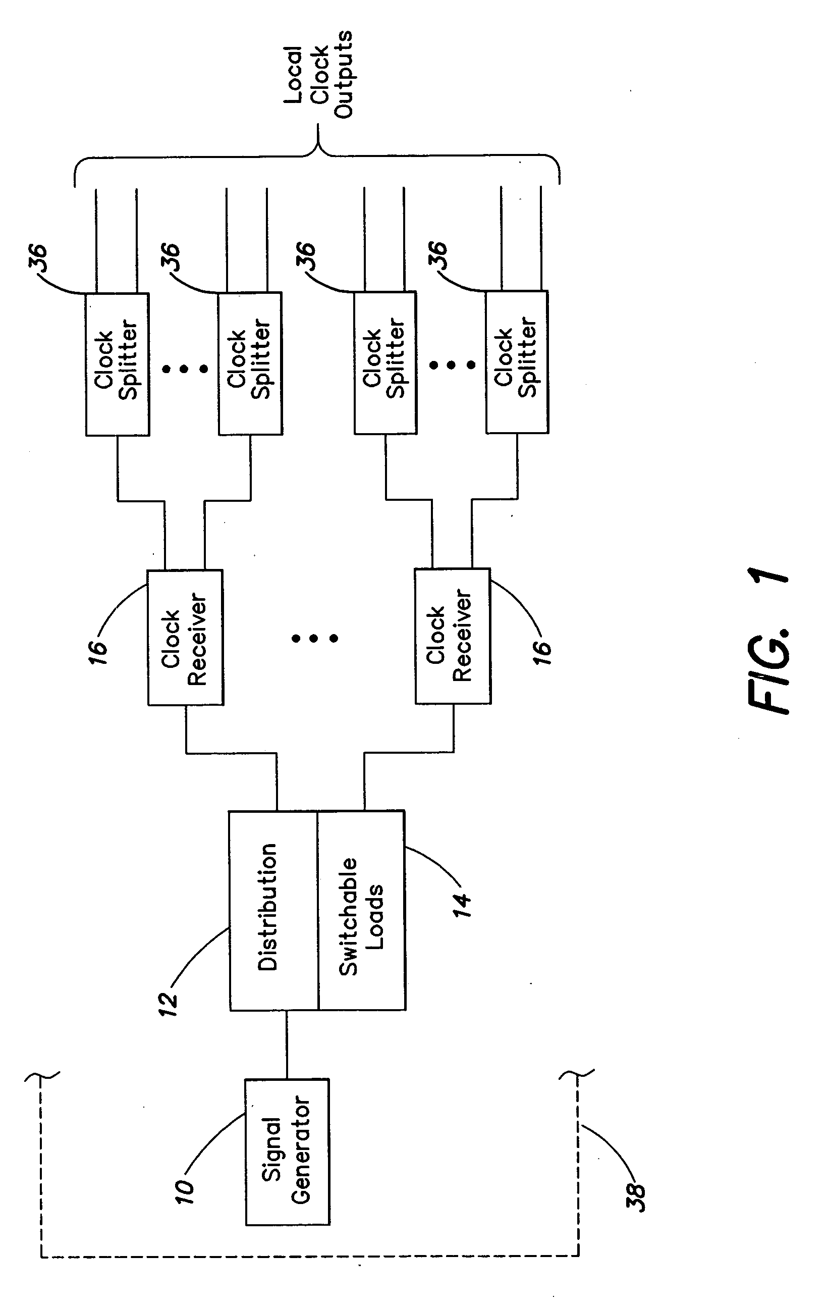
[0014]FIG. 1 is a schematic block diagram representation of a clock signal generation and distribution arrangement provided in accordance with the invention.

[0015] In FIG. 1, reference numeral 10 indicates a signal generator which generates a differential sinusoidal signal pair. As is well understood by those who are skilled in the art, a differential sinusoidal signal pair comprises a pair of sinusoidal wave forms, that are substantially equal in frequency and amplitude but that are substantially 180° out of phase with each other, as illustrated in FIG. 3. The differential sinusoidal signal pair generated by signal generator 10 may, for example, have a peak to peak differential (ppD) of about 100 mV or 150 mV. The common mode level of the differential sinusoidal signal pair may be at the center of the power supply voltage. For example, each signal of the pair may swing from about 575 mV to 625 mV when a 1.2 volt power supply is used. It will be recognized that such a differential ...


PUM


Abstract

A differential sinusoidal signal pair is generated on an integrated circuit (IC). The differential sinusoidal signal pair is distributed to clock receiver circuits, which may be differential amplifiers. The clock receiver circuits receive the differential sinusoidal signal pair and convert the differential sinusoidal pair to local clock signals. Power consumption and noise generation are reduced as compared to conventional clock signal distribution arrangements.

Description

[0001] This application is a continuation of U.S. patent application Ser. No. 09 / 682,473 filed Sep. 6, 2001, which is hereby incorporated by reference herein in its entirety.FIELD OF THE INVENTION [0002] This invention is concerned with integrated circuits (ICs), and is more particularly concerned with distribution of clock signals on an IC. BACKGROUND OF THE INVENTION [0003] At the current state of the art, processors are operating at clock rates of 1 GHz or higher, and further advances in operating rates can be anticipated. However, at current and expected future clock rates, noise generation and power consumption are significant issues in connection with clock signal distribution. For example, in one processor operating at 1 GHz, the power consumption of the clock tree accounts for about 75% of the power consumed by the chip. [0004] Furthermore, with conventional clock distribution techniques it has been considered desirable to limit the amount of clock gating employed in process...

Claims


Application Information

Patent Timeline
Patent Type & Authority Applications(United States)
IPC IPC(8): G06F1/04G06F1/10
CPCG06F1/10
Inventor BONACCIO, ANTHONY RICHARDCOHN, JOHN MAXWELLDEAN, ALVAR ANTONIOFARRAHI, AMIR H.HATHAWAY, DAVID J.VENTRONE, SEBASTIAN THEODORE
Owner GLOBALFOUNDRIES INC
Features
  • R&D
  • Intellectual Property
  • Life Sciences
  • Materials
  • Tech Scout
  • Unparalleled Data Quality
  • Higher Quality Content
  • 60% Fewer Hallucinations
Learn More