Coil-embedded dust core

a technology of dust core and coil, applied in the direction of inductance, inductance with magnetic core, transformer/inductance coil/winding/connection, etc., can solve the problems of complex configuration of frames, difficult production, and high cost of facilities, and achieve smooth flow into all parts, no uneven compaction, and uniform degree of compaction

a technology of dust core and coil, applied in the direction of inductance, inductance with magnetic core, transformer/inductance coil/winding/connection, etc., can solve the problems of complex configuration of frames, difficult production, and high cost of facilities, and achieve smooth flow into all parts, no uneven compaction, and uniform degree of compaction

US20060038651A1Inactive Publication Date: 2006-02-23ALPS ALPINE CO LTD

Image

  • Coil-embedded dust core
  • Coil-embedded dust core
  • Coil-embedded dust core

Examples


example

[0092] A mixed powder was used, in which 95.7 percent by weight of soft magnetic alloy powder having a composition of Fe74.9Ni3Sn1.5P10.8C8.8B1, 4 percent by weight of acrylic acid resin, and 0.3 percent by weight of lubricant were mixed. The soft magnetic alloy powder used here was a powder produced by quenching an alloy melt having the above-described composition ratio. The powder was in an amorphous state and had a particle diameter of 3 to 150 μm.

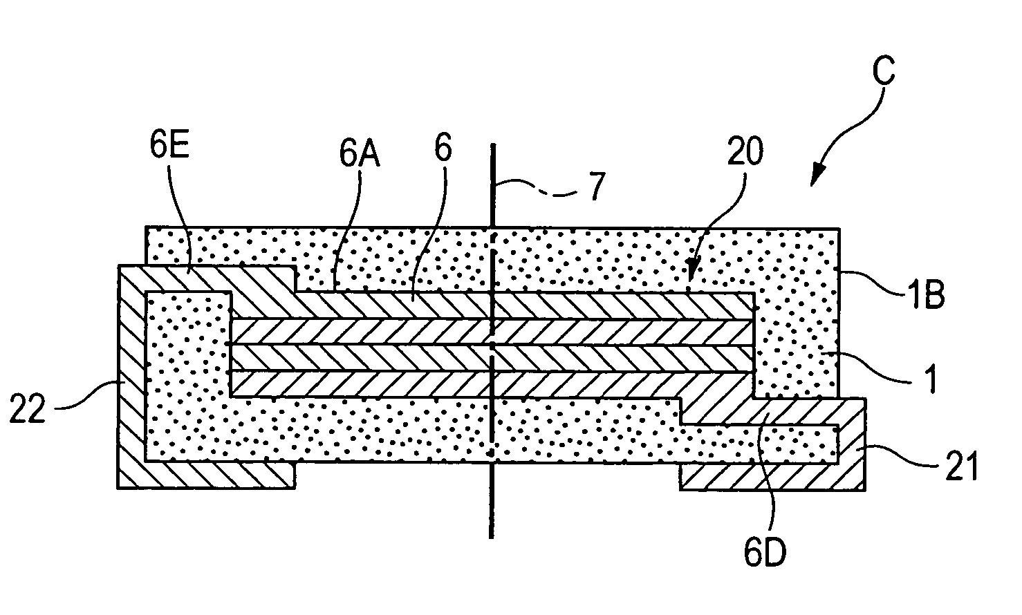
[0093] A flat type conductor wire made of Cu of 0.4 mm in thickness and 1.5 mm in width was edgewise wound5 turns to form a coil main body having an inner diameter of 4.1 mm and an outer diameter of 7.9 mm. The flat type conductor wire at the end portion of the uppermost layer of the coil main body was bent downward, the flat type conductor wire at the end portion of the lowermost layer was bent downward, and the resulting coil was set in the device shown in FIG. 7. The above-described mixed powder was filled in around the coil, and a ...


PUM


Abstract

A coil-embedded dust core of the present invention is provided with a molded coil component including a coil main body having a structure in which a flat type conductor wire is wound edgewise, one end side terminal portion disposed by being lead in the thickness direction of the coil main body, the other end side terminal portion, one end side leading electrode portion disposed by extending the one end side terminal portion, and the other end side leading electrode portion disposed by extending the other end side terminal portion; and a dust core composed of a soft magnetic alloy powder disposed covering the coil main body, the one end side terminal portion, and the other end side terminal portion of the molded coil component.

Description

[0001] This application claims the benefit of priority to Japanese Patent Application No. 2004-241477 filed on Aug. 20, 2004, herein incorporated by reference. BACKGROUND OF THE INVENTION [0002] 1. Field of the Invention [0003] The present invention relates to a coil-embedded dust core having a structure in which a metal coil is covered with a soft magnetic alloy powder compact. [0004] 2. Description of the Related Art [0005] Requirements for small and high-performance dust cores to be mounted on electronic equipment have become intensified as miniaturization and weight reduction of the electronic equipment have been advanced. The dust core is produced by molding a soft magnetic alloy powder, e.g., a ferrite powder, having a high saturation magnetic flux density into a desired shape through compaction. [0006] In order to produce a smaller and higher-performance inductor provided with this dust core, it has been proposed to construct a structure in which a metal coil is embedded in t...

Claims


Application Information

Patent Timeline
23 Feb 2006
Publication
US20060038651A1
IPC
H01F27/02
CPC
H01F17/04; H01F27/027; H01F27/2847; H01F2017/048; H01F41/0246; H01F2017/046; H01F27/292
Inventors
MIZUSHIMA, TAKAO; NAITO, YUTAKA