
Process, system and software arrangement for determining at least one location in a sample using an optical coherence tomography

a technology of optical coherence tomography and process, applied in the field of imaging using optical coherence tomography, can solve the problems of inability to eliminate or significantly reduce the motion of the sample, undesirable variations in the position of the entire eye, and difficult to visualize, so as to facilitate the variable transmission of optical paths

Inactive Publication Date: 2006-02-23
THE GENERAL HOSPITAL CORP
View PDF99 Cites 208 Cited by
  • Summary
  • Abstract
  • Description
  • Claims
  • Application Information

AI Technical Summary

Benefits of technology

[0013] In another exemplary embodiment of the present invention, a delay arrangement can be provided which is associated with the sample and / or the reference, and facilitates variable transmissive optical paths therein. Further, at least a section of a particular path of the sample and / or the reference may be non-reciprocal. The reference can receive radiation via a path that is different from a path along which the radiation is transmitted from the reference.

Problems solved by technology

However, such biological samples may often contain irregular surfaces and structures that can make imaging problematic.
In addition, a motion of the sample may further compounds this problem.
However, this means that it is often impossible to eliminate or significantly reduce the motion of the sample relative to the imaging device.
Referring to the example of retinal imaging, any slight motion on the part of the subject whose retina is being imaged would likely result in undesirable variations in position of the entire eye, in addition to the topological variations inherent in the eye itself.
However, using this approach may have the effect of degrading the signal-to-noise ratio and sensitivity of the image.
However, the detection of such prior techniques was not robust.

Method used


Image

  • Process, system and software arrangement for determining at least one location in a sample using an optical coherence tomography
  • Process, system and software arrangement for determining at least one location in a sample using an optical coherence tomography
  • Process, system and software arrangement for determining at least one location in a sample using an optical coherence tomography

Examples


Embodiment Construction

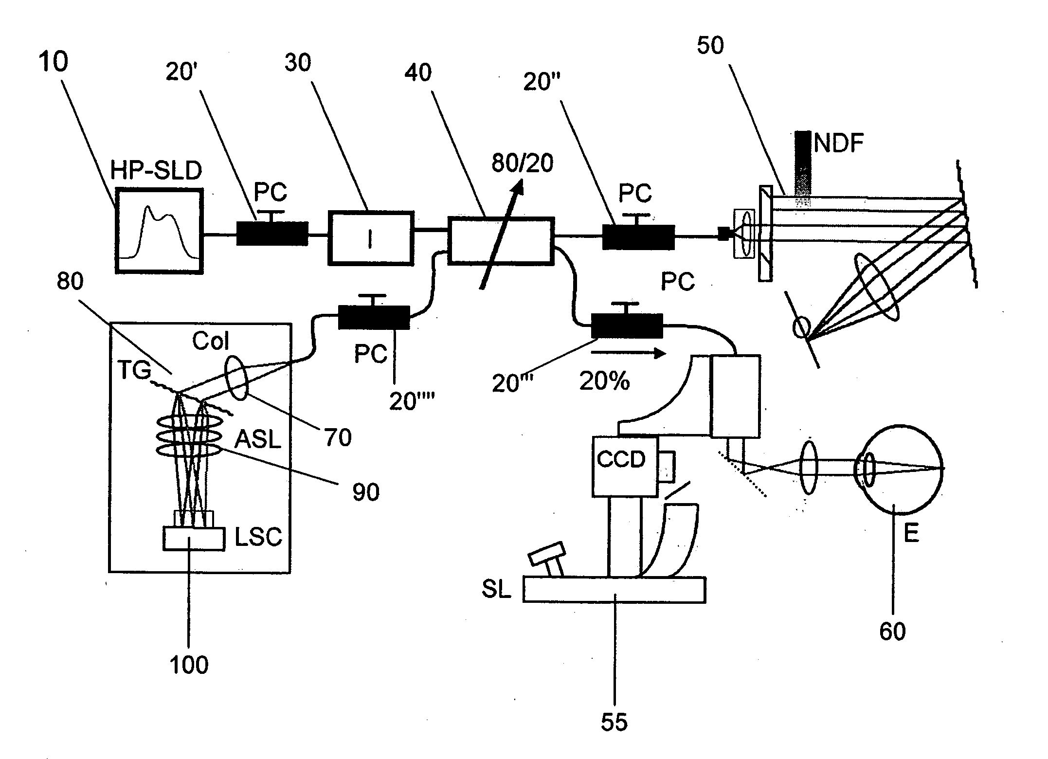
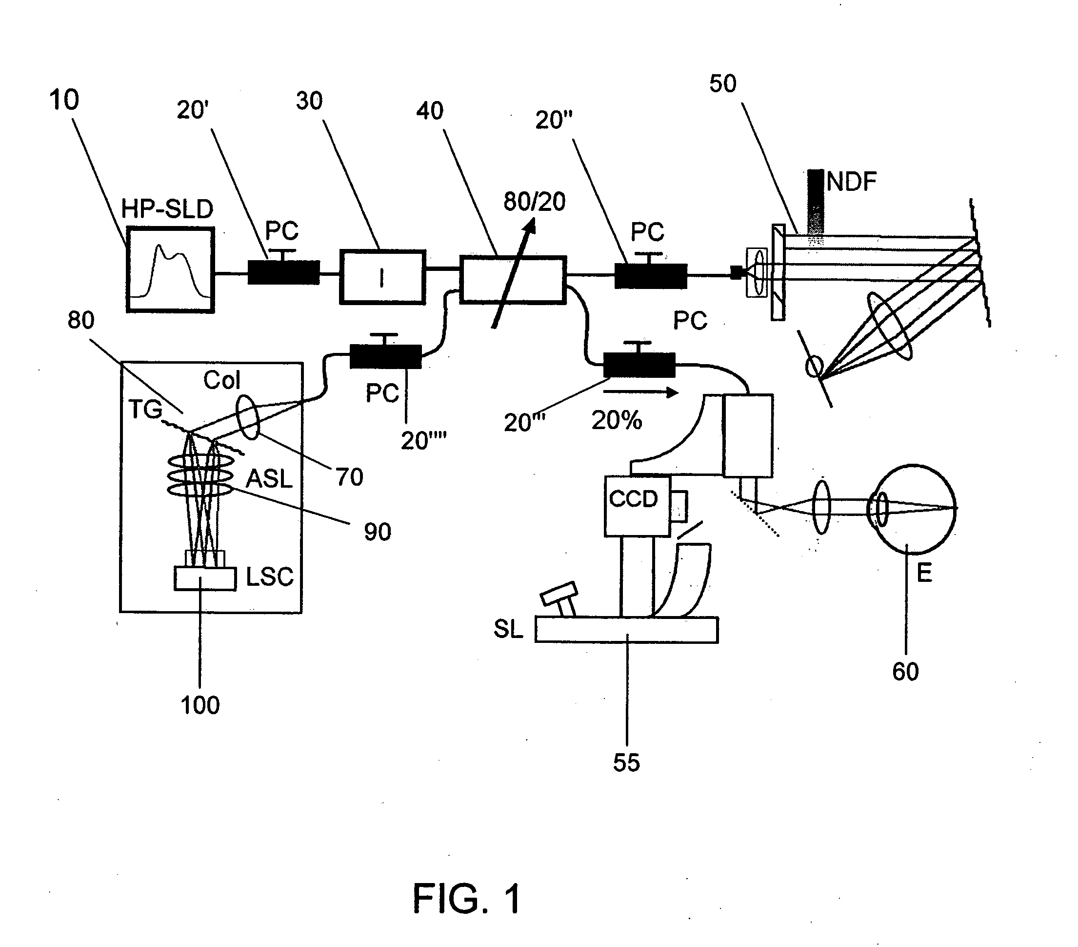
[0031]FIG. 1 shows an exemplary embodiment of a sample configuration of a spectral domain optical coherence tomography (“SD-OCT”) arrangement which can be used for implementing the exemplary embodiments of the system, process and software arrangement according to the present invention. A detailed description of operation of this arrangement is described in detail in International Patent Publication No. WO 03 / 062802. In particular, as shown in FIG. 1, a high-powered superluminescent diode source (“HP-SLD”) 10 generates an electro-magnetic radiation or light signal which is transmitted through a first polarization controller (“PC”) 20′ and an optical isolator 30 so as to facilitate a one way propagation of an electro-magnetic energy to reach a signal splitter 40. The signal splitter forwards one portion of the split signal to a reference arm (which includes a second PC 20″, a reference, certain optics and a neutral density filter (“NFD”) 50) and another portion of the split signal to ...


PUM


Abstract

A system, process and software arrangement are provided to determine at least one position of at least one portion of a sample. In particular, information associated with the portion of the sample is obtained. Such portion may be associated with an interference signal that includes a first electromagnetic radiation received from the sample and a second electro-magnetic radiation received from a reference. In addition, depth information and / or lateral information of the portion of the sample, may be obtained. At least one weight function can be applied to the depth information and / or the lateral information so as to generate resulting information. Further, a surface position, a lateral position and / or a depth position of the portion of the sample may be ascertained based on the resulting information.

Description

CROSS-REFERENCE TO RELATED APPLICATION(S) [0001] The present application claims priority from U.S. Patent Application Ser. No. 60 / 599,809 filed Aug. 6, 2004, the entire disclosure of which is incorporated herein by reference. This application also relates to U.S. Patent Publication No. 2002 / 0198457, the entire disclosure of which is incorporated herein by reference.FIELD OF THE INVENTION [0002] The present invention relates generally to imaging using optical coherence tomography (“OCT”), and more particularly to processes, systems and software arrangements which are capable of determining at least one location in a sample using OCT technique(s). BACKGROUND OF THE INVENTION [0003] Optical coherence tomography (“OCT”) is an imaging technique that can measure an interference between a reference beam of light and a detected beam reflected back from a sample. A detailed system description of convention time-domain OCT has been provided in Huang et al. “Optical coherence tomography,” Scie...

Claims


Application Information

Patent Timeline
IPC IPC(8): G01B9/02
CPCA61B3/1005A61B3/102A61B3/1225G01N21/4795G01B9/02004G01B9/02044G01B2290/45G01B9/02067G01B9/02011G01B9/02068G01B9/02069G01B2290/70G01B9/02083G01B9/02091A61B3/12G01B9/02G01B11/24
Inventor DE BOER, JOHANNES FITZGERALDPARK, BORIS HYLE
Owner THE GENERAL HOSPITAL CORP
Learn More