Polarization-selectively blazed, diffractive optical element

Inactive Publication Date: 2006-02-23
CARL ZEISS SMT GMBH
View PDF5 Cites 47 Cited by
  • Summary
  • Abstract
  • Description
  • Claims
  • Application Information

AI Technical Summary

Benefits of technology

[0006] The object is achieved by a polarization-selectively blazed, diffractive optical element comprising a plurality of contiguous blaze structures, which extend along a given geometrical path and each have a width perpendicular to their direction of extension, said width being greater than the wavelength of the electromagnetic radiation for which the diffractive optical element is designed, and each of said structures comprising a plurality of individual substructures, which are arranged next to each other according to a predetermined period in the direction of extension, said substructures providing the blaze effect and each having the shape, when viewed from above, of a closed geom

Problems solved by technology

However, so far, it has been very complex to g

Method used


Image

  • Polarization-selectively blazed, diffractive optical element
  • Polarization-selectively blazed, diffractive optical element
  • Polarization-selectively blazed, diffractive optical element

Examples


Embodiment Construction

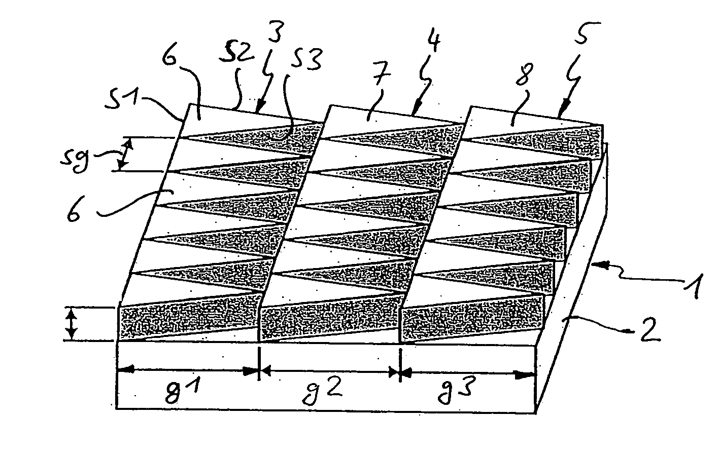
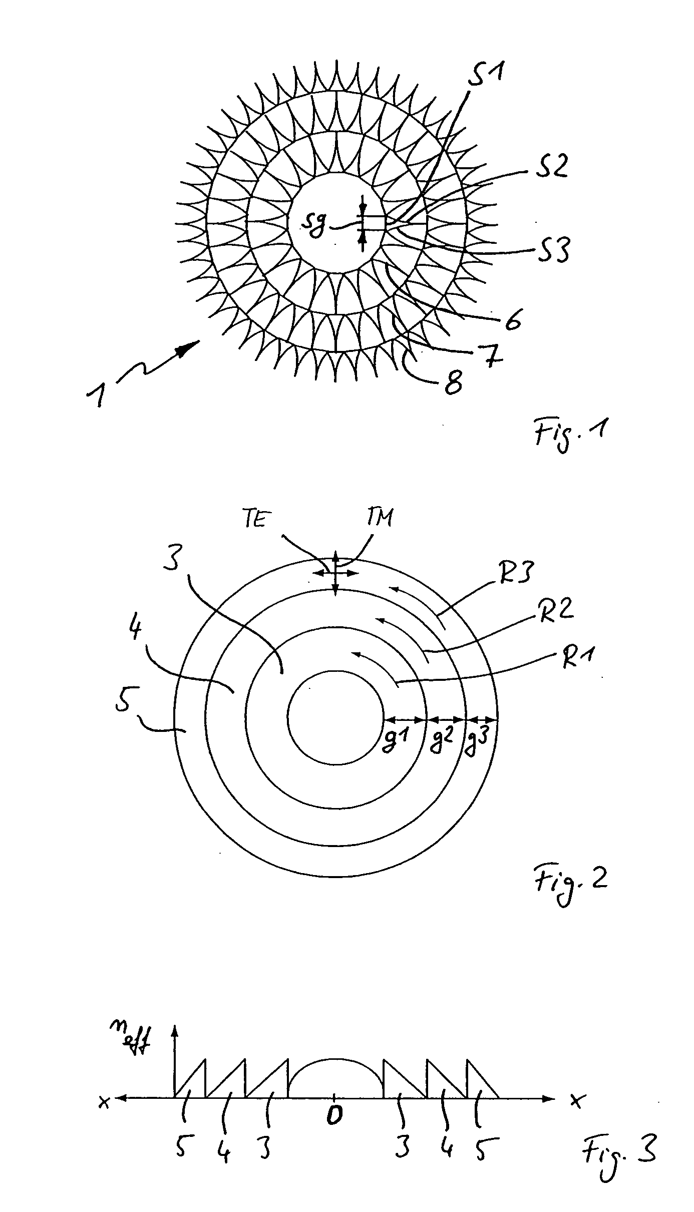
[0046] The polarization-selectively blazed, diffractive lens 1 shown in FIG. 1 comprises a transmissive carrier 2 having a refractive index n1, as shown, in particular, in FIG. 4. A multiplicity of circular ring-shaped blaze structures 3, 4, 5 of the carrier material are arranged on the upper surface of the carrier 2, said structures having widths g1, g2, g3, which are respectively greater than the wavelength of the electromagnetic radiation for which the lens 1 is optimized.

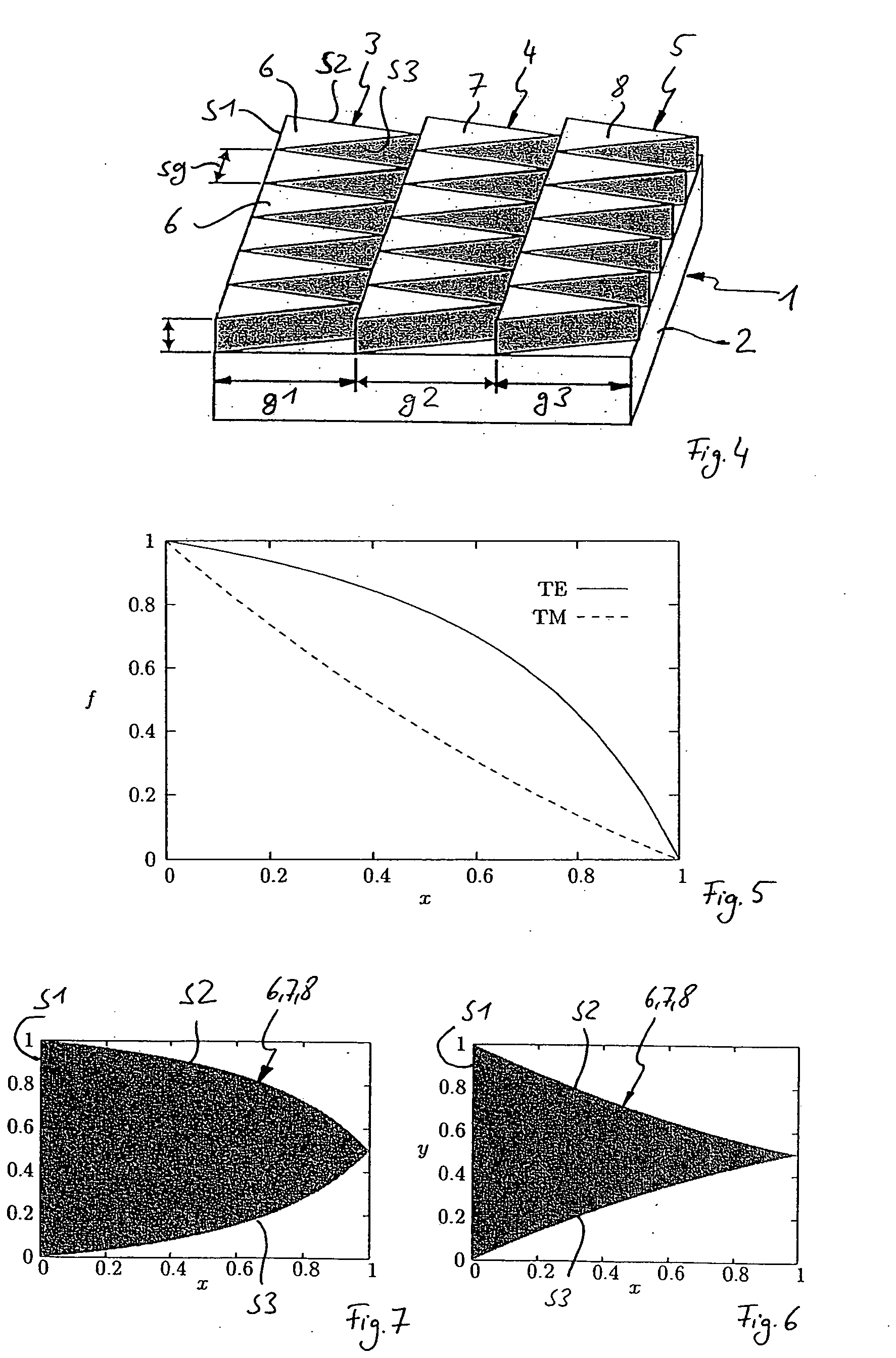
[0047] Each blaze structure 3, 4, 5 comprises a multiplicity of individual substructures 6, 7, 8, each having a substantially triangular shape and consisting of a different material preferably having a higher refractive index than the carrier material. When viewed from above, the individual substructures 6, 7, 8 thus comprise a base S1, respectively arranged parallel to the direction of extension of the blaze structures 3, 4, 5 (i.e., in this case, in the circumferential direction R1, R2, R3), as well as two fu...


PUM


Abstract

A polarization-selectively blazed, diffractive optical element is provided, comprising a plurality of contiguous blaze structures, which extend along a given geometrical path and each have a width (g1, g2, g3) perpendicular to their direction of extension (R1, R2, R3), said width being greater than the wavelength (X) of the electromagnetic radiation for which the diffractive optical element is designed, and each of said blaze structures comprising a plurality of individual substructures, which are arranged next to each other in the direction of extension (R1, R2, R3) according to a predetermined period (sg), said substructures providing the blaze effect and each having the shape, when viewed from above, of a closed geometrical surface whose dimension parallel to the direction of extension (R1, R2, R3) varies perpendicular to the direction of extension (R1, R2, R3), but is always smaller than the wavelength (X) of the electromagnetic radiation, and whose maximum dimension perpendicular to the direction of extension (R1, R2, R3) is greater than the wavelength (X) of the electromagnetic radiation, wherein the filling ratio (f) of the individual substructures in the direction of extension (R1, R2, R3) relative to the period (sg) is selected such, as a function of the position perpendicular to the direction of extension (R1, R2, R3), that the blaze effect is optimized for one of two mutually orthogonal polarization conditions of the electromagnetic radiation.

Description

FIELD OF THE INVENTION [0001] The invention relates to a polarization-selectively blazed, diffractive optical element. BACKGROUND OF THE INVENTION [0002] Focused light beams are employed in many optical fields, such as lithography, confocal microscopy, optical data storage, for example, or in optical particle traps. It is important in all of these applications to obtain the smallest possible focusing radius, which can be achieved only by the use of high-aperture optical systems. In this connection, it is increasingly important, however, to consider the polarization properties of the electromagnetic field. Thus, for example, in the case of a linearly polarized, high-aperture light beam, the energy distribution in the focus no longer has rotation symmetry to the optical axis, but is elliptically deformed. A particular shape of the intensity and polarization distribution in the focus can be achieved by specifically setting the polarization distribution within the cross-section of the l...

Claims


Application Information

Patent Timeline
IPC IPC(8): G02B5/18
CPCG03F7/70566G03F7/70316
Inventor RUOFF, JOHANNESKLEEMANN, BERND
Owner CARL ZEISS SMT GMBH
Why Eureka
Try Eureka