Radial-flow turbine wheel

a technology of radial flow turbine and turbine wheel, which is applied in the direction of liquid fuel engine, vessel construction, marine propulsion, etc., can solve the problems of deteriorating turbine efficiency, driving loss, deteriorating turbine efficiency, etc., and achieve the effect of improving the turbine efficiency

Inactive Publication Date: 2006-02-23
HANWHA POWER SYST CO LTD
View PDF10 Cites 41 Cited by
  • Summary
  • Abstract
  • Description
  • Claims
  • Application Information

AI Technical Summary

Benefits of technology

[0009] The present invention provides a radial-flow turbine wheel capable of improving a turbine efficiency.

Problems solved by technology

However, an excessive formation of such scallops 60 results in deterioration of turbine efficiency.
Since the exhaust gas colliding against the periphery 10a or leaked toward a back area B does not function as energy to drive the turbine wheel 30, there is a driving loss, which deteriorates turbine efficiency.

Method used


Image

  • Radial-flow turbine wheel
  • Radial-flow turbine wheel
  • Radial-flow turbine wheel

Examples


Embodiment Construction

[0024] Reference will now be made in detail to describe a radial-flow turbine wheel according to preferred embodiments of the present invention.

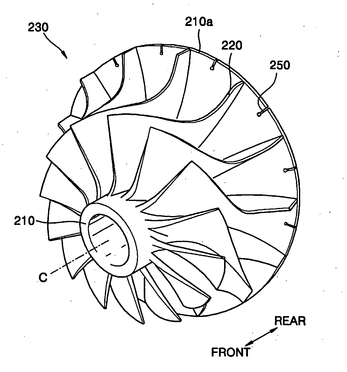
[0025]FIG. 4 shows a turbine wheel 130 according to one embodiment of the present invention. Referring to FIG. 4, turbine wheel 130 includes a hub 110 and a plurality of turbine blades 120 formed around the hub 110 at constant intervals.

[0026] Hub 110 has an outer radius gradually increased from front to rear. The hub 110 includes a rear side periphery 110a (hereinafter, called a “rear periphery”) radially extending in a plane perpendicular to center axis C. A rotary shaft (not shown) supporting the turbine wheel 130 is inserted into the center of the hub 110, and rotational energy is transferred from the turbine wheel 130 through the rotary shaft to a compressor wheel coaxially coupled to the rotary shaft. The hub 110 supports the plurality of turbine blades 120 formed-around the hub.

[0027] The turbine blades 120 convert pressure energy ...


PUM


Abstract

A radial-flow turbine wheel is provided. The radial-flow turbine wheel includes a hub having an outer radius gradually increasing from a front end to a rear end, a rear periphery of the hub being radially extended in a plane generally perpendicular to a center axis, and a plurality of turbine blades formed around the hub at constant intervals. A plurality of slots is formed by inward cut at the rear periphery of the hub between the turbine blades of the hub. The turbine wheel restrains creation and propagation of crack due to thermal stress, as well as improving a turbine efficiency.

Description

BACKGROUND OF THE INVENTION [0001] This application claims the priority of Korean Patent Application No. 2004-65881, filed on Aug. 20, 2004, in the Korean Intellectual Property Office, the disclosure of which is incorporated herein in its entirety by reference. [0002] 1. Field of the Invention [0003] The present invention relates to a radial-flow turbine wheel, and more particularly, to a radial-flow turbine wheel capable of restraining creation and propagation of a crack due to thermal stress, as well as improving a turbine efficiency. [0004] 2. Description of the Related Art [0005] In general, a gas turbine is powered by expansion of an operating fluid of high temperature and high pressure, which is generated from the combustion process of a combustor, to drive a compressor coupled coaxially to the gas turbine. In an internal combustion engine with a turbocharger, a high-pressure gas compressed by the compressor is supplied to a fuel cell or a combustion cylinder of the internal c...

Claims


Application Information

Patent Timeline
Patent Type & Authority Applications(United States)
IPC IPC(8): B64C27/46
CPCF01D5/048F01D5/147F01D5/16F05D2220/40F05D2220/50F05D2250/291F05D2260/941F01D5/26
Inventor KIM, KYUNG-HEUI
Owner HANWHA POWER SYST CO LTD
Why Eureka
Try Eureka