
Operation button for endoscope

a technology of endoscope and operation button, which is applied in the field of operation button for endoscope, can solve the problems of narrowing the tube, affecting the operation, and affecting the operation, and causing the tube to narrow

Inactive Publication Date: 2006-02-23
ASAHI KOGAKU KOGYO KK
View PDF12 Cites 37 Cited by
  • Summary
  • Abstract
  • Description
  • Claims
  • Application Information

AI Technical Summary

Benefits of technology

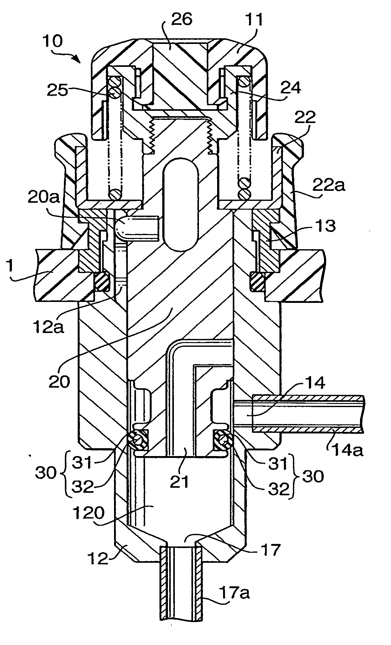
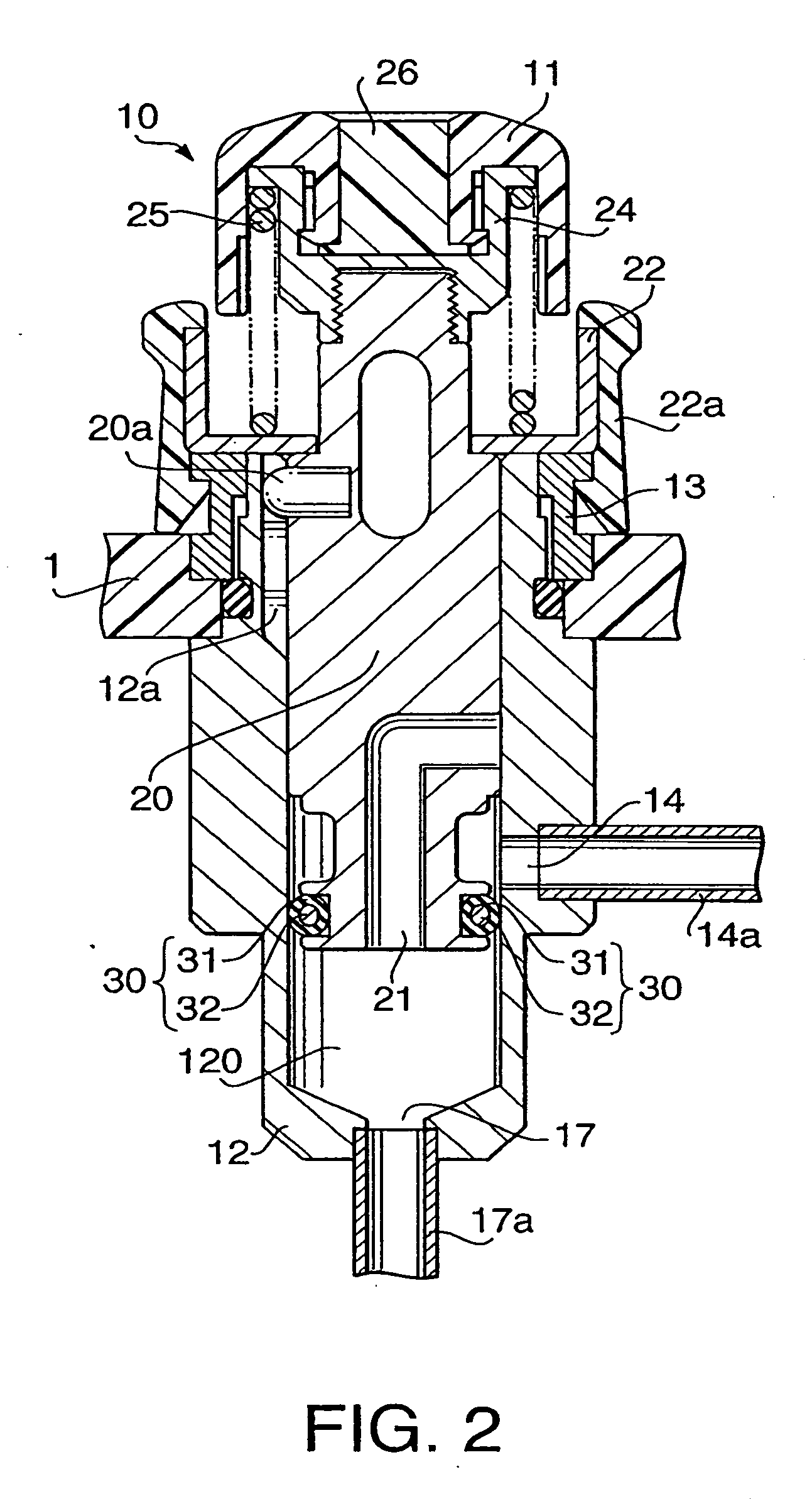
[0007] According to an aspect of the present invention, there is provided with an operation button for an endoscope that is provided with a cylinder that is provided with a lumen, and a first flow channel and a second flow channel that are communicating with the lumen, a piston that is installed inside the lumen of the cylinder to reciprocally slide between a first position, whereat the first flow channel is prevented from communicating with the second flow channel, and a second position, whereat the first flow cha

Problems solved by technology

However, according to the conventional structure, the lubricant should be applied repetitively to the surface of the O-ring after every certain period of time, which may be troublesome and inconvenient.
In addition, too much amount of lubricant applied may leak to other connecting tubes and consequentially narrow the tubes.

Method used


Image

  • Operation button for endoscope
  • Operation button for endoscope
  • Operation button for endoscope

Examples


first embodiment

[0018] Referring to the accompanying drawings, an embodiment of the present invention will be described. In the following description, the lower end of each section shown in FIG. 1 is referred as distal end, while the upper end of each section is referred as proximal end.

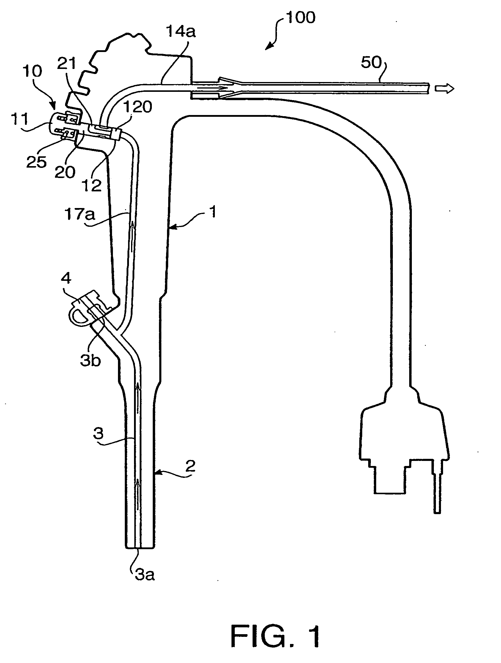
[0019]FIG. 1 shows an endoscope 100 including an operation section 1, which is to be held by hand for operation of the entire endoscope 100, and an insertion section 2, which is provided at the distal end of the operation section 1 to be inserted into a cavity of a tubular organ.

[0020] The insertion section 2 is provided with a channel tube 3 penetrating through the inside thereof. The distal end 3a of the channel tube 3 (i.e., at the distal end of the insertion section 2) is provided with an opening. On the other end, a proximal end portion 3b is fixed in the vicinity to the connecting point of the operation section 1 and the insertion section 2, and a clamp stopper 4 is equipped thereto.

[0021] An aspiration but...

experimental embodiments

ADDITIONAL EXPERIMENTAL EMBODIMENTS

[0048] Additional experimental embodiments according to the present invention are described below.

experimental embodiment 1

[0049] A coating layer (average thickness: 5 micrometers) configured with poly-para-xylylene is formed to be an O-ring (i.e., a sealing member) by applying Xylene solution including poly-para-xylylene (polymerization degree: greater than 5,000) to the surface of a core member (diameter: 0.2 mm) which is configured with silicone rubber, and allowed to dry.

[0050] Then, the O-ring is embedded to an aspiration button (i.e., “OF-B120” manufactured by PENTAX Corp.), and installed in an endoscope (i.e., “EG-2930” manufactured by PENTAX Corp).


PUM


Abstract

An operation button for an endoscope is provided with a cylinder and a piston reciprocally slidable inside a lumen of the cylinder. A first flow channel and a second flow channel are formed to communicate with the lumen. When the piston is located at a first position, the first and second flow channel communicate with each other, while the first flow channel and the second flow channel are disconnected when the piston is located at a second position. A sealing member is provided on an outer periphery of the piston to provide secure airtightness between the cylinder and the piston. The sealing member includes a core member mainly made of one of poly-para-xylylene and poly-para-xylylene derivatives and a coating layer allocated on an outer periphery of the core member.

Description

BACKGROUND OF THE INVENTION [0001] The present invention relates to an operation button for an endoscope. [0002] An endoscope is configured to have several features for operations such as to aspirate liquid, for example body fluid or blood from body cavities, and to provide certain gas or fluid into body cavities. These operations are generally carried out by pressing a button (an operation button) that is equipped to an endoscope. [0003] Such a button equipped to an endoscope is configured with a cylinder, a piston that is installed to reciprocally slide inside the cylinder, and an O-ring for maintaining airtightness between the cylinder and the piston. An example of such a structure is disclosed in Japanese Patent Provisional Publication No. 2000-271067. [0004] Generally, an O-ring is made of an elastic material. If such a material has large friction resistance, lubricant such as silicone oil is applied to the surface of the O-ring. [0005] However, according to the conventional st...

Claims


Application Information

Patent Timeline
IPC IPC(8): A61B1/12
CPCA61B1/015A61B1/00068
Inventor SATO, YASUYUKI
Owner ASAHI KOGAKU KOGYO KK
Learn More