
Sealed shaft gravity buoyancy energy system and method of use thereof

a technology of gravity buoyancy and energy system, which is applied in the direction of motors, machines/engines, mechanical equipment, etc., can solve the problems of large energy expenditure, pause in operation, undesired idle time, etc., and achieve the effect of avoiding depletion of non-renewable energy sources and being easy to size up to different power and/or energy requirements

Inactive Publication Date: 2006-03-02
VILLALOBOS VICTOR
View PDF37 Cites 40 Cited by
  • Summary
  • Abstract
  • Description
  • Claims
  • Application Information

AI Technical Summary

Benefits of technology

[0012] Accordingly, a feature and advantage of the present invention is its ability to generate energy.
[0013] Another feature and advantage of the present invention is its ability to be utilized for stationary or motive power generation.
[0014] Still another feature and advantage of the present invention is its ability to be easily sized to different power and / or energy requirements.
[0015] Yet another feature and advantage of the present invention is its use of readily available materials and components.
[0016] Yet still another feature and advantage of the present invention is that it reduces, and potentially avoids depletion of non-renewable energy sources.

Problems solved by technology

The principal difficulty with pumping devices, such as that of Chih-Chiang '978, is the need to raise the fluid head, thereby requiring a large expenditure of energy and further causing a pause in the operation; that is, an undesired idle time.
Gilmore '242 exhibits the difficulties of maintaining a seal between the air and fluid media, and does not teach a means for hermetically sealing the buoyancy shaft, while allowing the transportation of the weights up the shaft.
However, such devices are limited to use where waves are generated or otherwise available.

Method used


Image

  • Sealed shaft gravity buoyancy energy system and method of use thereof
  • Sealed shaft gravity buoyancy energy system and method of use thereof
  • Sealed shaft gravity buoyancy energy system and method of use thereof

Examples


Embodiment Construction

[0033] In describing the preferred and selected alternate embodiments of the present invention, as illustrated in FIGS. 1-12, specific terminology is employed for the sake of clarity. The invention, however, is not intended to be limited to the specific terminology so selected, and it is to be understood that each specific element includes all technical equivalents that operate in a similar manner to accomplish similar functions.

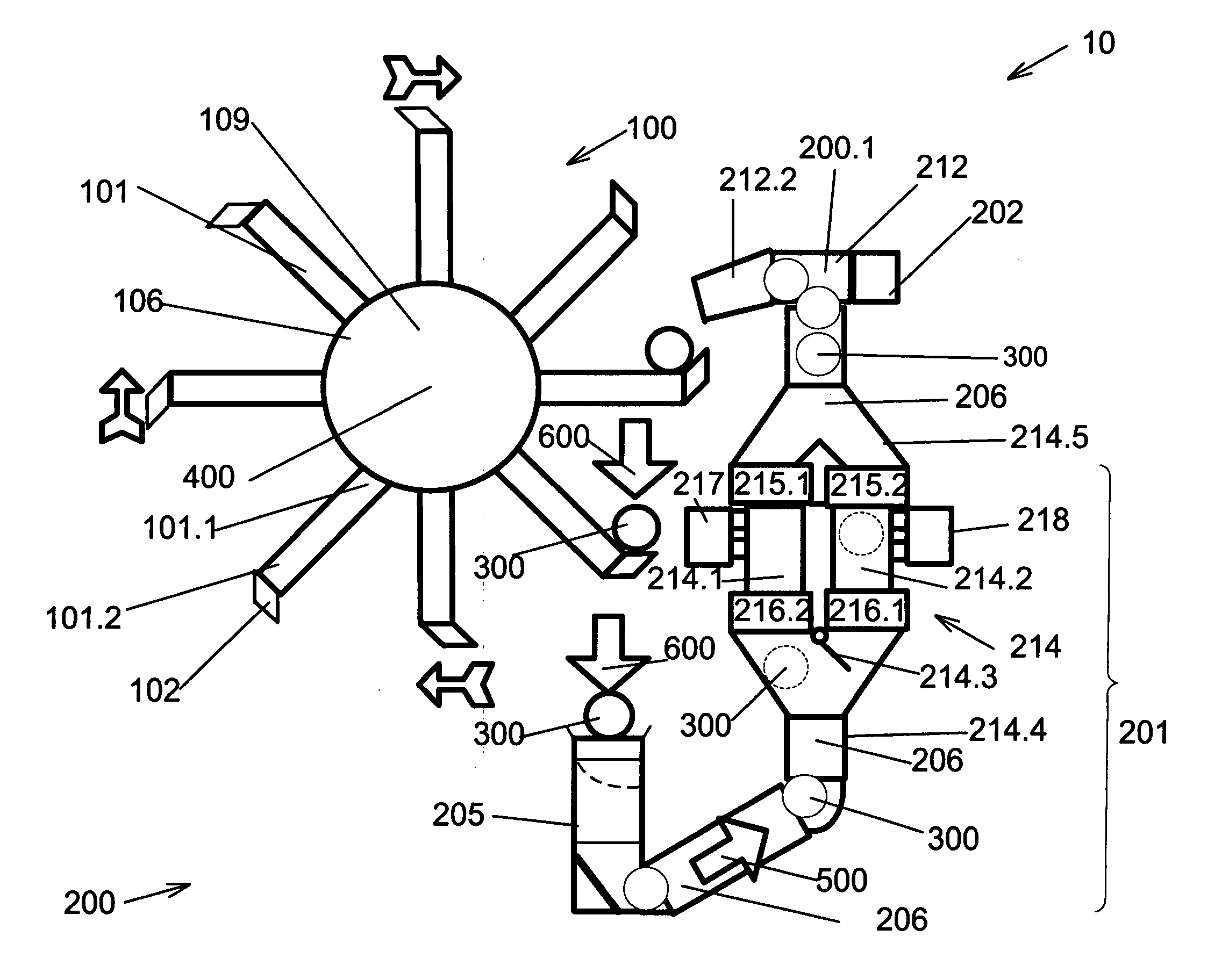
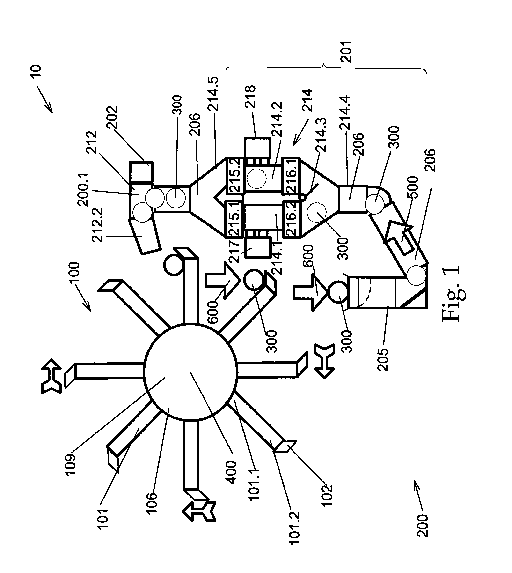
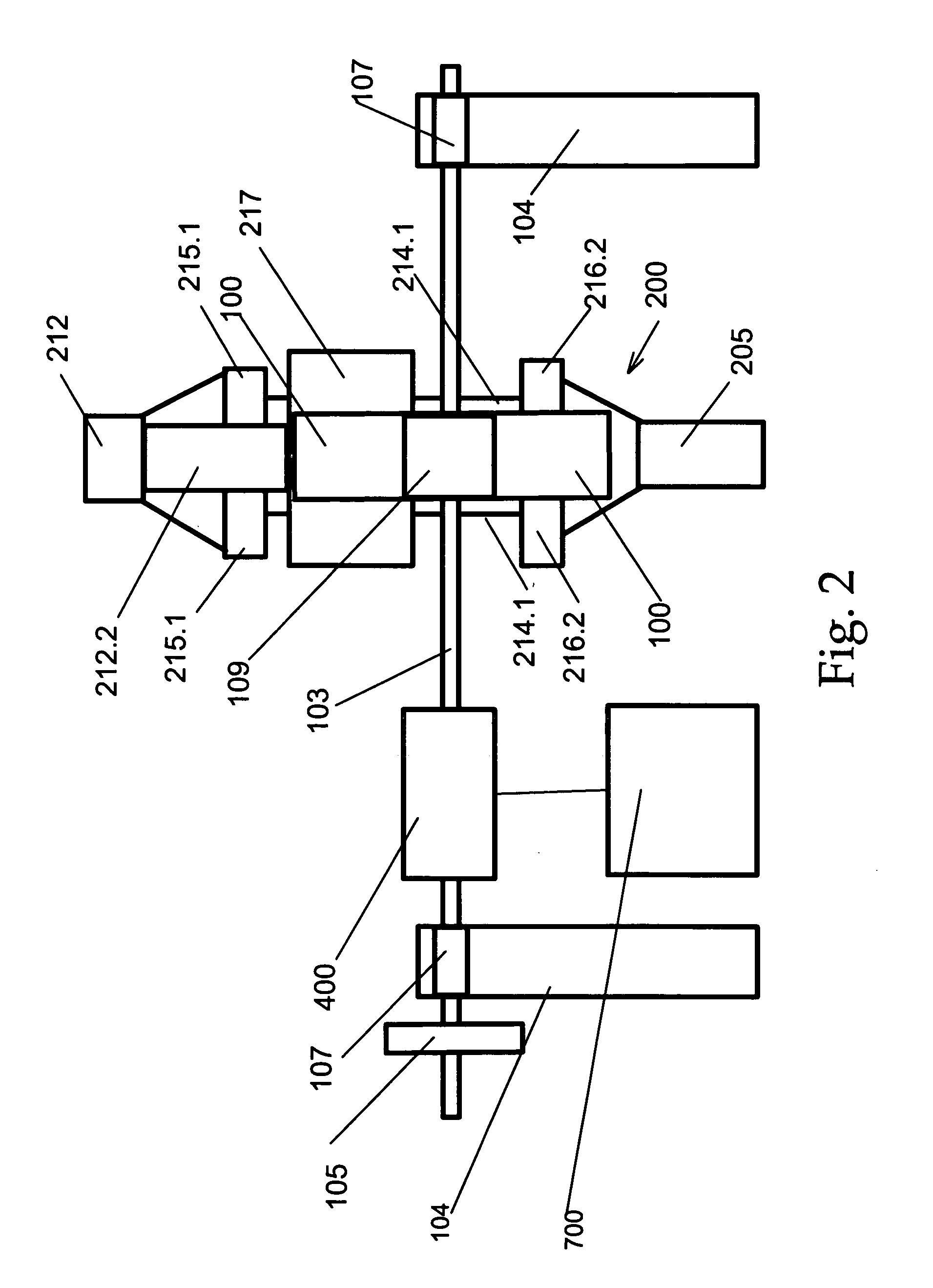
[0034] Referring now to FIGS. 1-9, the present invention in a preferred embodiment is gravity-buoyancy generator 10 comprising wheel 100, electrical generator 400, balls 300, collector box 205, and buoyancy shaft 200, wherein collector box 205 and buoyancy shaft 200 have fluid 206 disposed therewithin. Buoyancy shaft 200 comprises hermetically-sealed double-shaft box 214, first tank 217, and second tank 218.

[0035] Referring now more particularly to FIG. 1, wheel 100 comprises spoke arms 101 having first ends 101.1 and second ends 101.2, wherein first ends ...


PUM


Abstract

A sealed-shaft gravity-buoyancy energy system and method of use thereof, wherein a wheel is powered by ball masses which fall under gravitational force, thereby causing the wheel to rotate. The ball masses are collected and inserted into a fluid shaft, wherein the fluid shaft comprises at least two separate columns having valves at the ends thereof to provide a sealing function, thereby preventing fluid loss. Buoyant force raises the ball masses to the top of the device, wherein the ball masses are deposited once again onto the wheel. A generator or other device utilizes the rotational force of the wheel to create energy.

Description

CROSS-REFERENCE AND PRIORITY CLAIM TO RELATED APPLICATIONS [0001] To the fullest extent permitted by law, the present non-provisional patent application claims priority to, and the full benefit of, non-provisional patent application entitled “Gravity Buoyancy Energy Generator”, filed on Apr. 13, 2004, having assigned Ser. No. 10 / 822,963. A request pursuant to 37 C.F.R. §1.53(c) (2) has been filed to convert application Ser. No. 10 / 822,963 to a provisional application. Further, to the fullest extent permitted by law, the present non-provisional patent application claims priority to, and the full benefit of provisional patent application entitled “Gravity Buoyancy Energy Generator”, filed on May 6, 2004, having assigned Ser. No. 60 / 568,554, to provisional patent application entitled “Sealed Shaft Gravity Buoyancy Energy Generator”, filed on May 18, 2004, having assigned Ser. No. 60 / 572,082, and to provisional patent application entitled “Sealed Shaft Gravity Buoyancy Energy Generator”...

Claims


Application Information

Patent Timeline
IPC IPC(8): F03B17/02
CPCF03B17/04Y02E10/20F03G7/10F03G3/02
Inventor VILLALOBOS, VICTOR
Owner VILLALOBOS VICTOR
Learn More