Self-cleaning mechanical filter

a filter and self-cleaning technology, applied in the direction of filtration separation, sedimentation settling tank, separation process, etc., can solve the problem that the cleaning cannot be achieved solely by suction, and achieve the effect of sufficient cleaning, effective cleaning, and sufficient cleaning

Active Publication Date: 2006-03-02
AJ BASSTECH
View PDF12 Cites 38 Cited by
  • Summary
  • Abstract
  • Description
  • Claims
  • Application Information

AI Technical Summary

Benefits of technology

[0008] The present invention provides a self-cleaning mechanical filter that can be operated for a long period of time.
[0010] Using this arrangement, injection of backwash water from the backwash nozzle can be performed in synchronization with suction through the suction nozzle. In this way, sufficient cleaning of the filter may be accomplished even when, due to the nature of the raw water, such sufficient cleaning cannot be achieved solely by suction through the suction nozzle. In other words, back clogging phenomenon in which suspended solids deposit on the filtrate side of the filter may be prevented reliably. Further, by moving the suction nozzle and the backwash nozzle in synchronization with one another, effective cleansing can be performed while maintaining sufficiently high speeds of backwash water injection and suction through the suction nozzle.

Problems solved by technology

In this way, sufficient cleaning of the filter may be accomplished even when, due to the nature of the raw water, such sufficient cleaning cannot be achieved solely by suction through the suction nozzle.

Method used


Image

  • Self-cleaning mechanical filter
  • Self-cleaning mechanical filter
  • Self-cleaning mechanical filter

Examples


Embodiment Construction

[0015] The present invention will next be described in connection with preferred embodiments with reference to the attached drawings.

[0016] It should be noted that the particulars set forth below are by way of example and only for the purpose of illustrative discussion of the preferred embodiments of the present invention. The following description is directed to facilitate understanding of the principles and conceptual aspects of the invention.

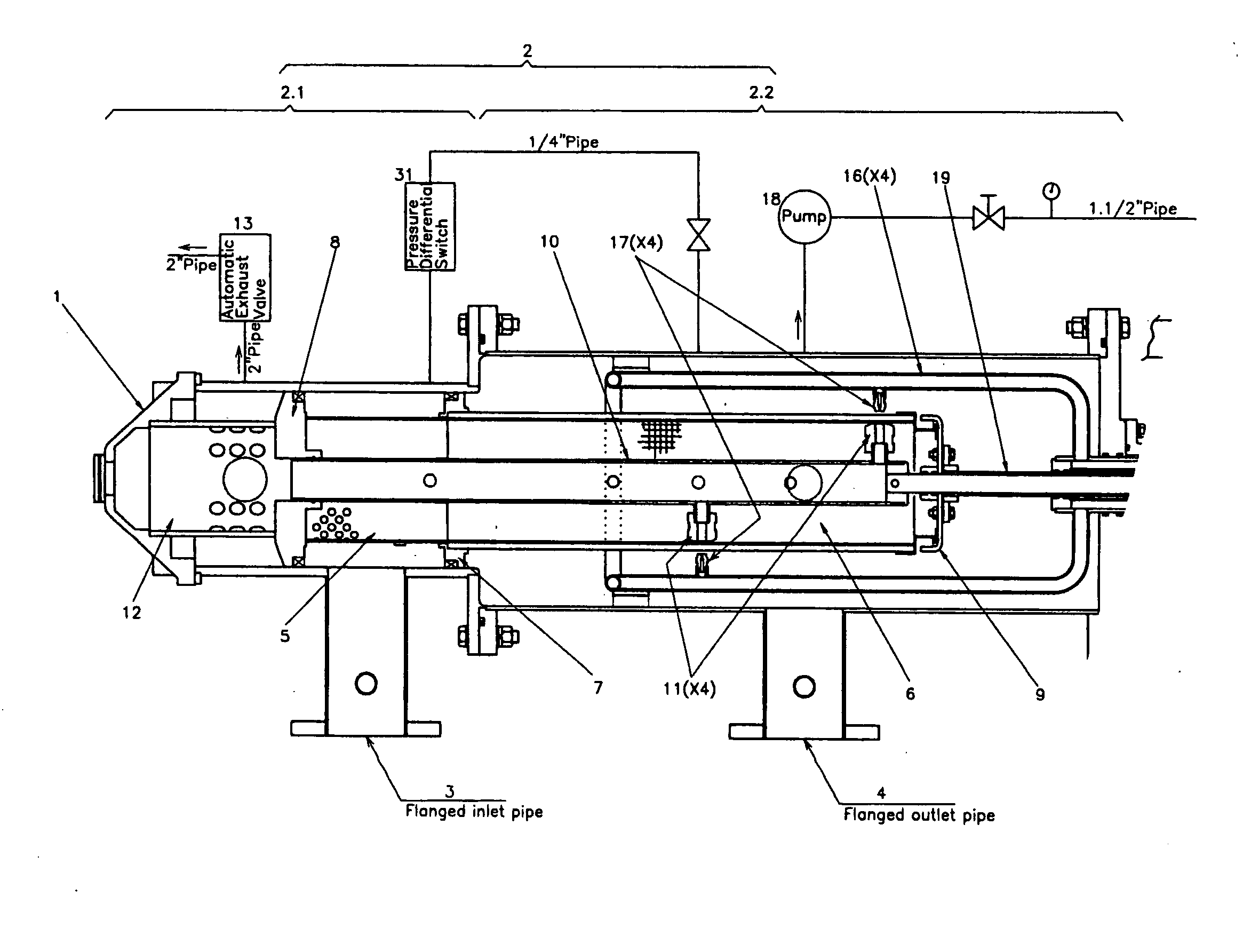
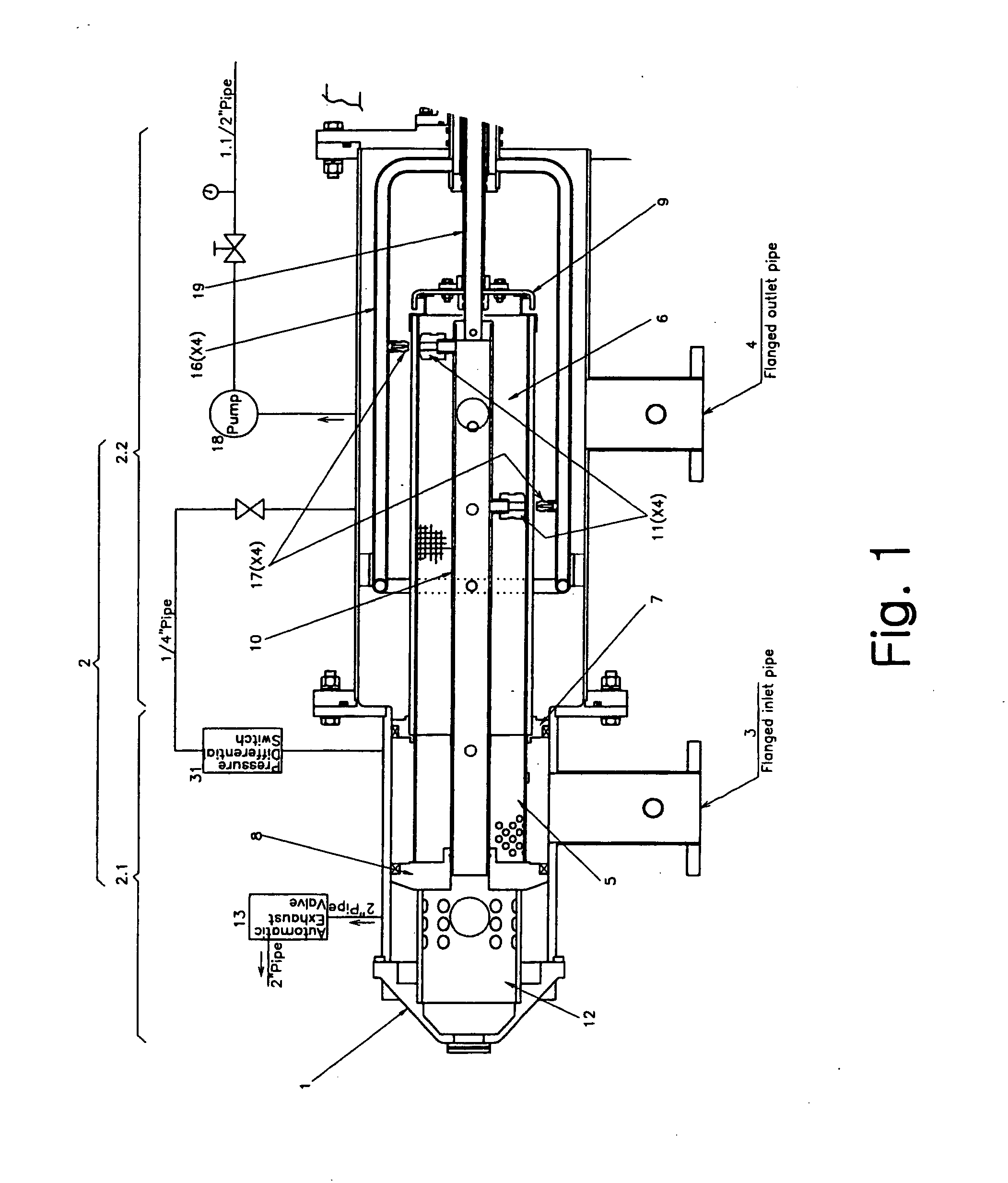
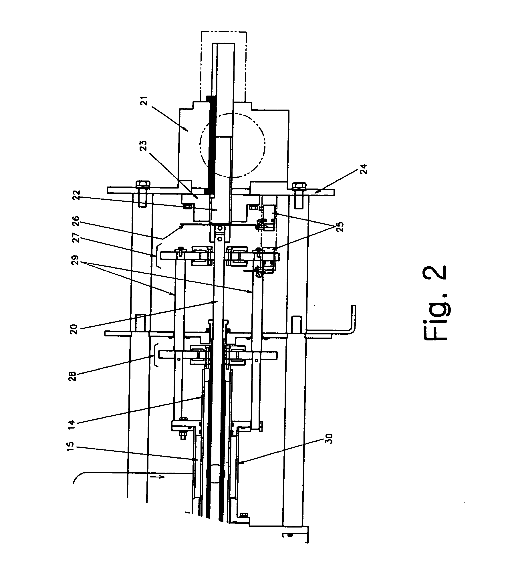
[0017]FIGS. 1, 2 and 5 show the overall structure of a filtering device according to a preferred embodiment. As can be seen in FIG. 1, a cylindrical filter housing 2 is composed of two parts, a small diameter housing section 2.1 and a large diameter housing section 2.2, for convenience of assembly. The small diameter housing section 2.1 includes a housing lid 1 which is detachable for maintenance operation, and an inlet pipe 3 for introducing liquid to be processed. The large diameter housing section 2.2 is provided with an outlet pipe 4 fo...


PUM

PropertyMeasurementUnit
aperture sizeaaaaaaaaaa
suctionaaaaaaaaaa

Abstract

A self-cleaning mechanical filter comprises a mechanism for simultaneously cleaning the internal surface and the external surface of a filter element. The filter is provided with structure for performing suction scanning of solid materials accumulated on the internal surface of the filter element, and structure which can be operated in synchronization with the suction scanning structure for backwashing the external surface of the filter element during a self-cleaning process.

Description

CROSS-REFERENCE TO RELATED APPLICATION [0001] The entire disclosure of Japanese Patent Application No. 2002-310706 including specification, claims, drawings and abstract is incorporated herein by reference in its entirety. BACKGROUND OF THE INVENTION [0002] 1. Field of the Invention [0003] The present invention relates to a filter for liquids, and more particularly to providing a highly efficient mechanical type self-cleaning filter. [0004] 2. Description of the Related Art [0005] Conventionally, many types of self-cleaning mechanical filters are used to remove suspended solids from solid-entrained liquids. One type among those filters is a cylindrical screen filter. In a cylindrical screen filter, a filter element having a cylindrical shape and bearing numerous perforations is placed within a sealed housing having inlet and outlet connections. In this arrangement, liquid introduced into the housing flows from the inside of the filter element out through the perforations in the filt...

Claims


Application Information

Patent Timeline
Patent Type & Authority Applications(United States)
IPC IPC(8): B01D29/68
CPCB01D29/15B01D2201/082B01D29/66B01D29/682B01D29/686
Inventor TAKATSUKA, MITSUO
Owner AJ BASSTECH
Why Eureka
Try Eureka