Three-dimensional confocal microscope

a confocal microscope and three-dimensional technology, applied in the field of three-dimensional confocal microscopes, can solve the problems of inability to correctly observe, unstable surface of sample, adverse vibrations affecting observation,

Inactive Publication Date: 2006-03-02
YOKOGAWA ELECTRIC CORP
View PDF2 Cites 17 Cited by
  • Summary
  • Abstract
  • Description
  • Claims
  • Application Information

AI Technical Summary

Benefits of technology

[0014] It is an object of this invention to solve the foregoing problems and to realize a three-dimensional confocal microscope capable of high-speed scanning in the direction of the optical axis without generating mechanical vibrations in a scanning unit for scanning in the direction of optical axis.

Problems solved by technology

However, since the conventional confocal microscope as described above uses moving units having moving parts such as actuator and motor, mechanical vibrations necessarily occur and such vibrations adversely affect the observation.
This would lead to a problem that the surface of the sample becomes unstable and cannot be correctly observed.
Moreover, in the conventional confocal microscope, since the moving speeds of the moving units are low and the scanning speed on the focal plane of the objective lens is as low as a few Hz, a three-dimensional confocal laser microscope for high-speed scanning cannot be realized.

Method used


Image

  • Three-dimensional confocal microscope
  • Three-dimensional confocal microscope
  • Three-dimensional confocal microscope

Examples


Embodiment Construction

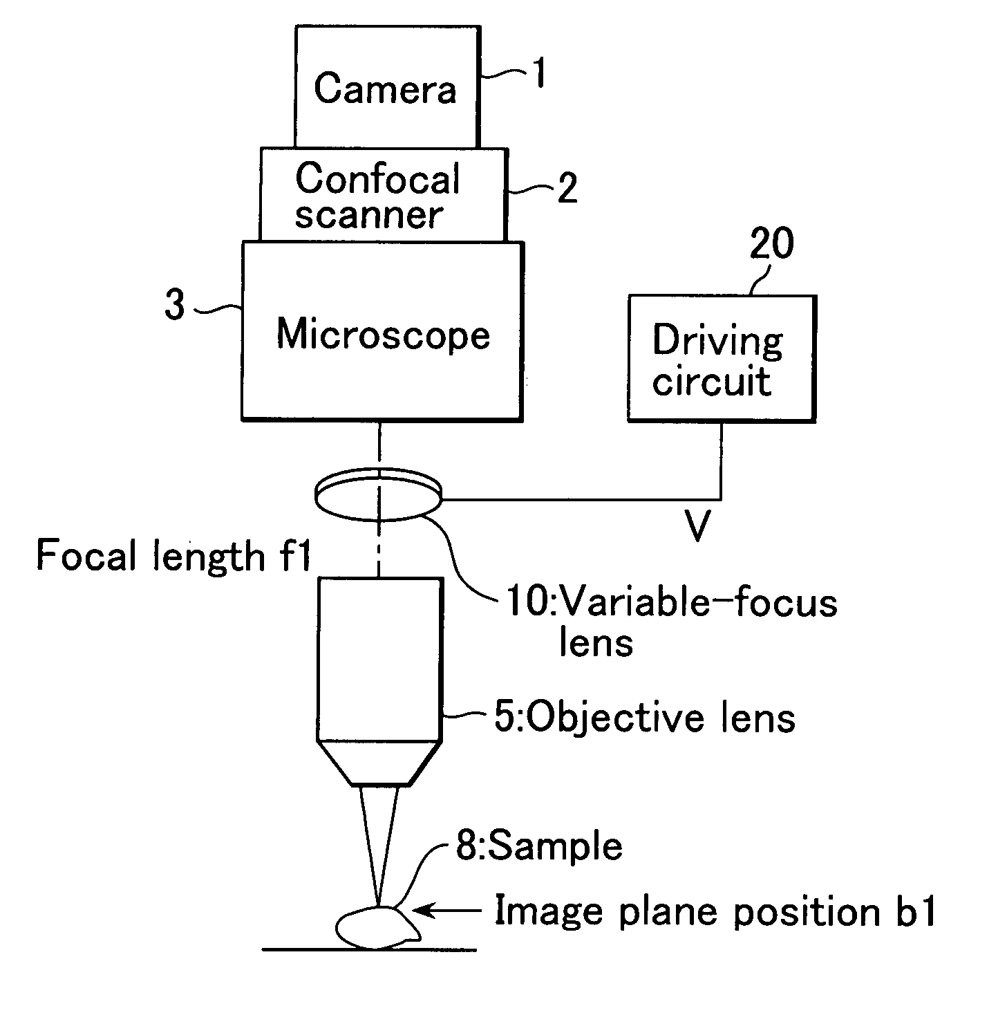
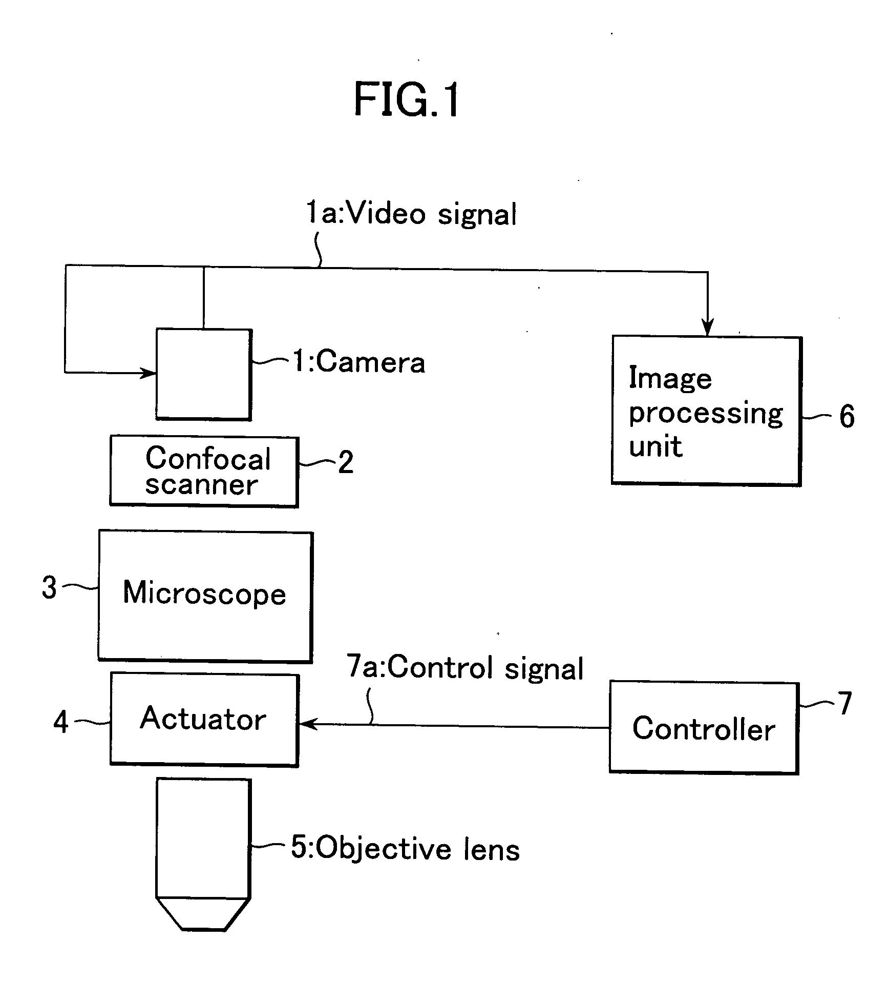
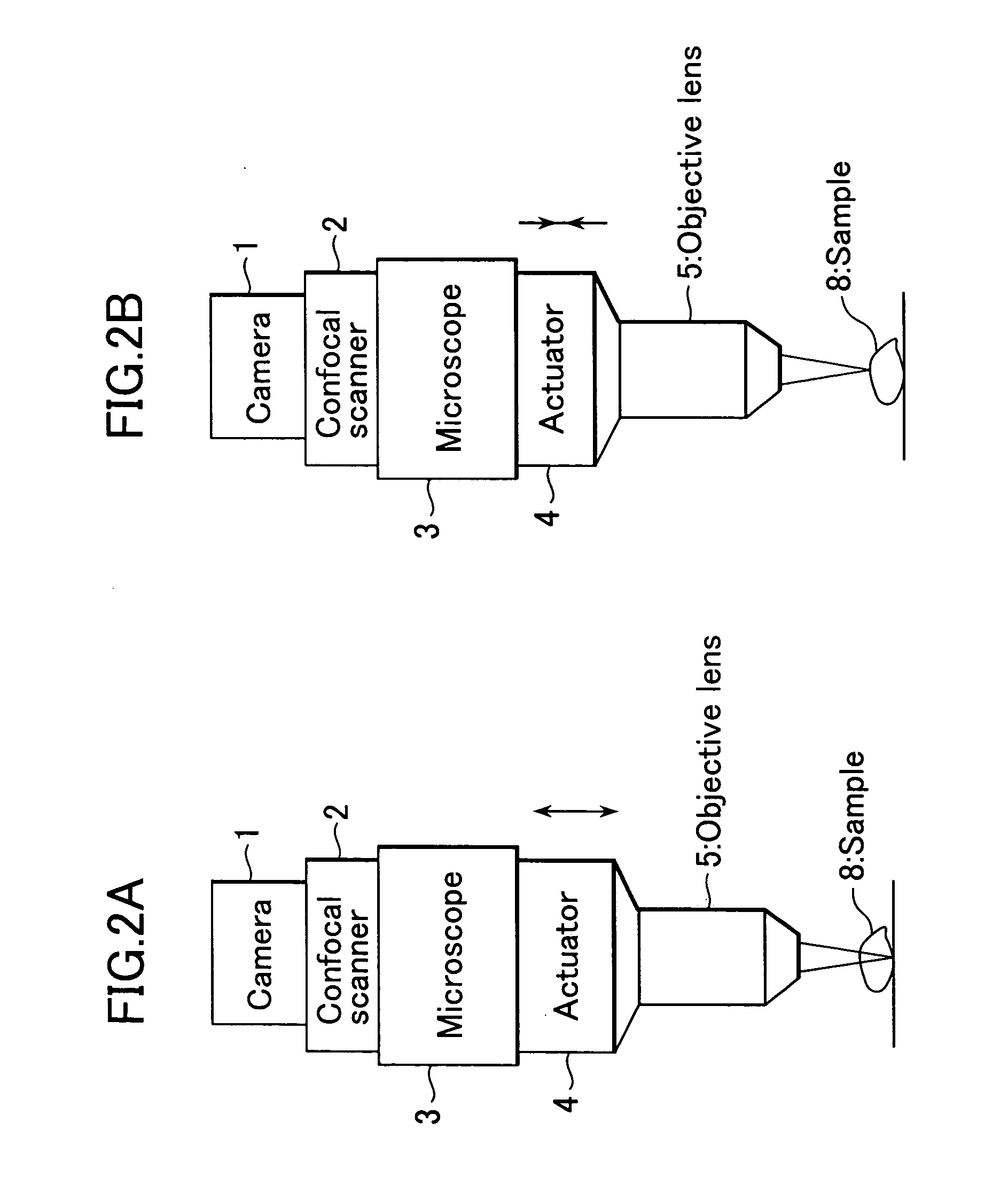
[0019] Hereinafter, this invention will be described in detail with reference to the drawings. FIGS. 3A and 3B are block diagrams showing an embodiment of a three-dimensional confocal microscope according to this invention. In this embodiment, since processing of an image picked up by a camera 1 is not directly related to this invention, the image processing unit of this invention, equivalent to the image processing unit 6 shown in FIG. 1, will not be shown in the drawings and will not be described in detail.

[0020] In FIGS. 3A and 3B, parts equivalent to those in FIG. 1 are denoted by the same numerals. FIGS. 3A and 3B differ from FIG. 1 in that a variable-focus lens of surface tension control type 10 and a driving circuit 20 are used instead of the actuator and the controller. The variable-focus lens of surface tension control type (hereinafter simply referred to as variable-focus lens) 10 is used as a field lens.

[0021]FIG. 4 shows a theoretical structural view (cross-sectional v...


PUM


Abstract

This invention realizes a three-dimensional confocal microscope in which mechanical vibrations do not occur in the scanning unit for scanning in the direction of optical axis, and in which scanning in the direction of optical axis can be carried out at a high speed. This invention has the following features. In the confocal microscope having a confocal scanner attached to an optical microscope and constructed to enable acquisition of an image of a sample as a confocal image by the confocal scanner, a variable-focus lens of surface tension control type having no moving part is uses as the field lens.

Description

BACKGROUND OF THE INVENTION [0001] 1. Field of the Invention [0002] This invention relates to a three-dimensional confocal microscope and particularly to a three-dimensional confocal microscope for observing the three-dimensional shape of an observation target. [0003] 2. Description of the Related Art [0004] By employing the Nipkow disk method that improves spatial resolution using a pinhole, a confocal microscope can condense light (laser beam) to a fine pinpoint illuminating the sample to be observed, and thus accurately measure one point in a three-dimensional space while eliminating redundant scattered light from the sample and poor focus. A confocal microscope of this type is described, for example, in JP-A-2002-72102. [0005] With such a three-dimensional confocal microscope, it is possible to acquire slice images of individual layers of a sample without actually cutting the sample very thinly and to construct a precise three-dimensional image from the slice image data. Therefo...

Claims


Application Information

Patent Timeline
Patent Type & Authority Applications(United States)
IPC IPC(8): G02B21/00
CPCG02B3/14G02B26/005G02B21/0084G02B21/006
Inventor AKIYAMA, TAKASHIKEI, TAKAYUKIMIKURIYA, KENTA
Owner YOKOGAWA ELECTRIC CORP
Why Eureka
Try Eureka