Prism assembly

a technology of prism and assembly, which is applied in the field of prism assembly, can solve the problems of large supplantation, high susceptibility to frequent breakdown, and difficult calibration

Active Publication Date: 2006-03-02
BARCO NV
View PDF4 Cites 64 Cited by
  • Summary
  • Abstract
  • Description
  • Claims
  • Application Information

AI Technical Summary

Benefits of technology

[0017] According to a preferred embodiment the outwardly orientated surfaces of the TIR-prisms and the outwardly oriented surfaces of the color prisms that are used for total internal reflection or partial spectral reflection of an image building part of the incoming light, are covered with an element that is spaced apart from said surface, such that a gap is defined in between said surface and said element, and wherein said gap is sealed with a seal that is applied on one of said prisms in order to prevent contaminants from entering said gap.

Problems solved by technology

In the past, cathode ray tube (CRT) projectors were used for most projection applications, but they have largely been supplanted, because they are large in size, difficult to calibrate, must be used in very dark surroundings, and have a high susceptibility to frequent breakdowns.
Liquid crystal display (LCD) is one technology used in digital projectors, but visible pixilation issues and larger size, compared to that of DLP, are negatives associated with LCD technology.
However, the prisms used in DLP projectors are highly sensitive to contamination.
The air gaps in the prism configuration are susceptible to accumulating these contaminants, which often results in the projection of visual artifacts, such as colored spots.
Contaminations can block light or nullify a TIR condition.
Cleaning the prisms from the contaminants is impractical, because of the high cost and difficulty of cleaning.
However, the '033 patent fails to provide a means of dissipating a sufficient amount of heat for normal projector operation when the light illuminates greater than 5,000 lumens.
If the heat is not sufficiently dissipated, sensitive optics may warp, which causes visual artifacts to appear on the projected images and other negative effects.
Excessive heat may also damage the DMD chips.

Method used


Image

  • Prism assembly
  • Prism assembly
  • Prism assembly

Examples


Embodiment Construction

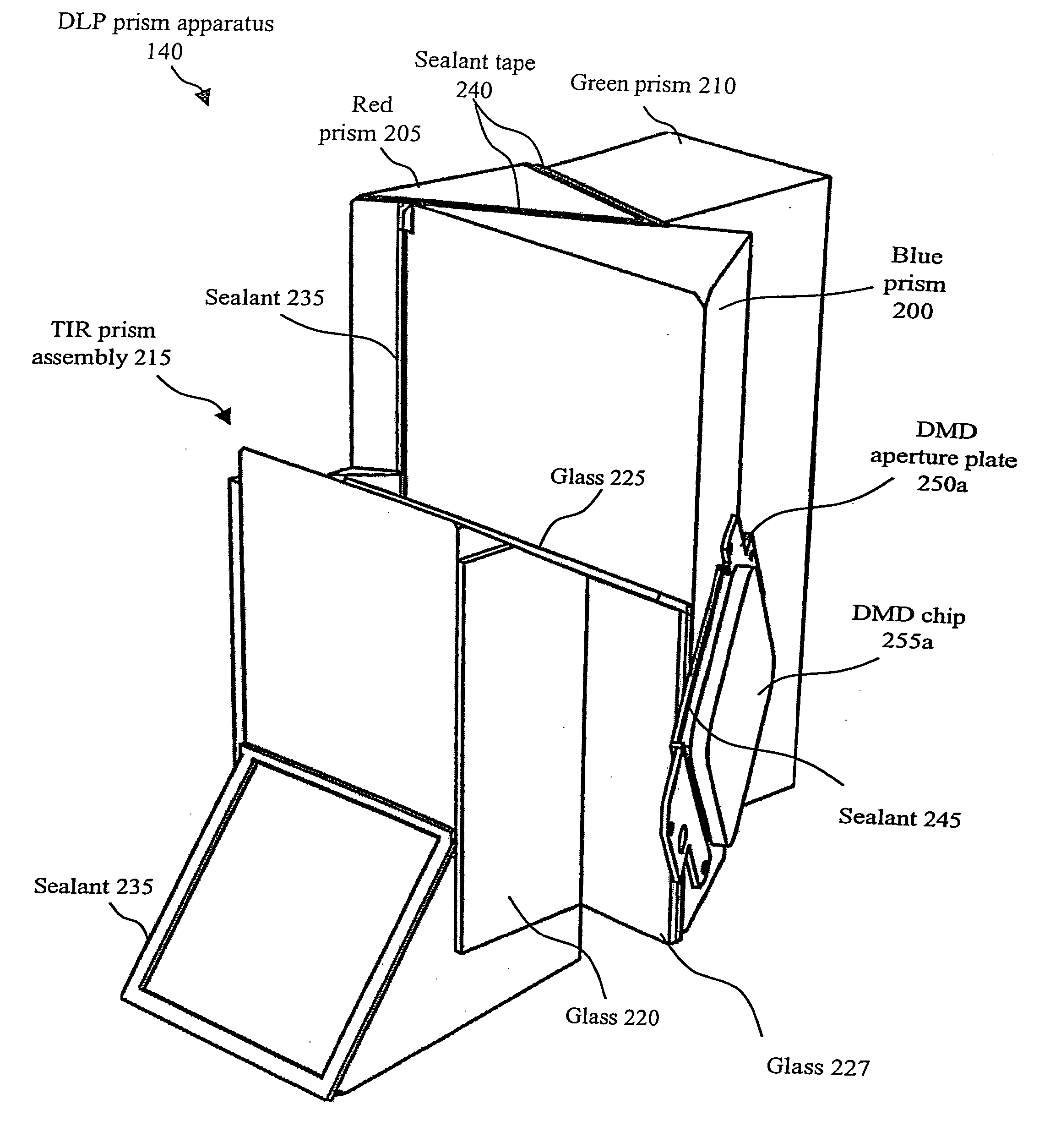
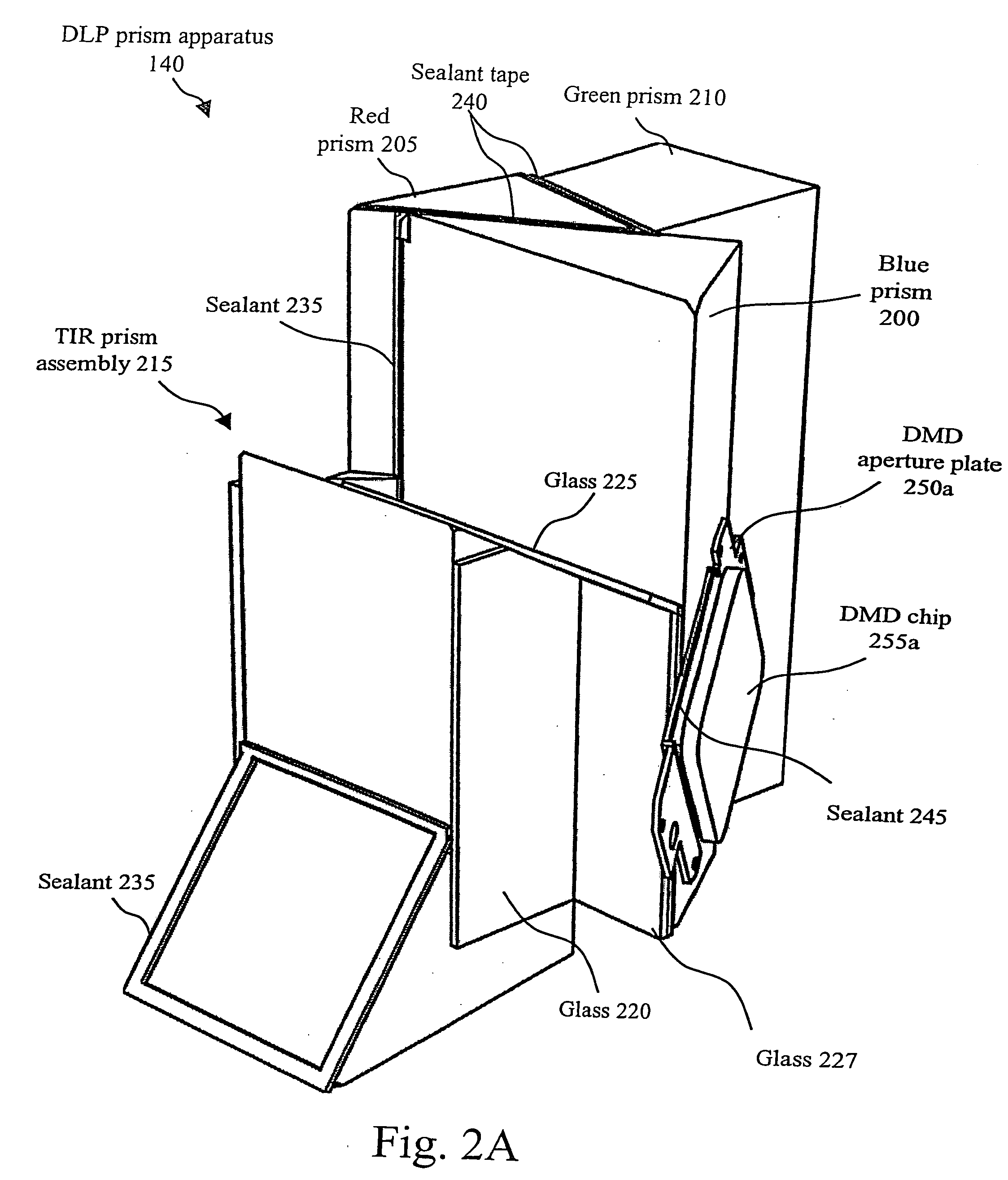
[0024] The present invention relates to sealing from atmospheric contaminants the air gaps, specifically, the air gaps between prisms and the air gaps between the prisms and the digital micro-mirror devices (DMD), in a digital light processing (DLP) engine.

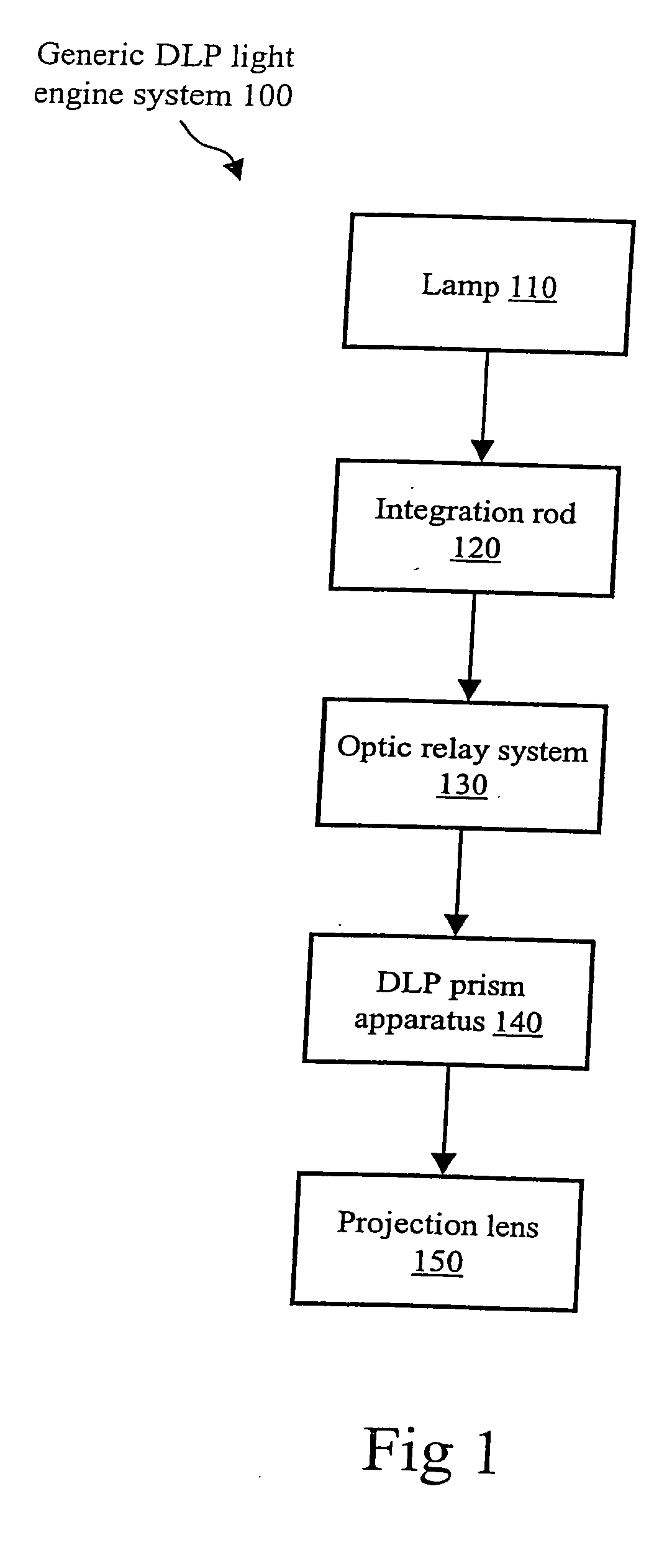
[0025]FIG. 1 illustrates a functional block diagram of a generic DLP light engine system 100. Generic DLP light engine system 100 includes a lamp 110, an integration rod 120, an optic relay system 130, a DLP prism apparatus 140, and a projection lens 150. Lamp 110 is a standard lamp that is used in digital projection systems, for example a mercury or xenon bulb lamp. Lamp 110 shines onto integration rod 120, which conditions and manages the light for even distribution. Optic relay system 130, a set of 4-6 lenses, transmits the light from integration rod 120 towards DLP prism apparatus 140. DLP prism apparatus 140 is formed of blue, red, and green prisms, DMD chips, and DMD aperture plates and is further described in reference to ...


PUM


Abstract

A prism assembly, including two or more prisms, at least one of which has or more surfaces that are used for total internal reflection or partial spectral reflection of incoming light, wherein at least a part of one of the surfaces used for reflection purposes is covered with an element that is spaced apart from the surface, such that a gap is defined in between the surface and the element, and wherein the gap is sealed with a seal that is applied on one of said prisms in order to prevent contaminants from entering the gap.

Description

BACKGROUND OF THE INVENTION [0001] 1. Field of the Invention [0002] The present invention relates to a prism assembly, more specifically a prism assembly consisting of two or more prisms, at least one of which comprises one or more surfaces that are used for total internal reflection or partial spectral reflection of incoming light. [0003] In particular the present invention relates to sealing from atmospheric contaminants the air gaps, specifically, the air gaps between prisms and the air gaps between the prisms and the light reflecting valves or more precisely digital micro-mirror devices (DMD), in a digital light processing (DLP) engine. [0004] 2. Discussion of the Related Art [0005] In the past, cathode ray tube (CRT) projectors were used for most projection applications, but they have largely been supplanted, because they are large in size, difficult to calibrate, must be used in very dark surroundings, and have a high susceptibility to frequent breakdowns. Digital projector sy...

Claims


Application Information

Patent Timeline
Patent Type & Authority Applications(United States)
IPC IPC(8): G02B5/04G02B27/00G02B27/10H04N5/74H04N9/31
CPCG02B5/04G02B17/04G02B27/0006H04N9/3197G02B27/145G03B21/00H04N9/3105G02B27/1026G03B21/005
Inventor VANDORPE, KRISTCOULIER, NICOGERETS, PETERLESSCHAEVE, STEFAN
Owner BARCO NV
Why Eureka
Try Eureka