Method and apparatus for performing lossless sensing of positive and negative peak inductor currents in a high side switch

a high-side switch and lossless sensing technology, which is applied in the direction of dc-dc conversion, power conversion systems, instruments, etc., can solve the problems of inability to handle both positive and negative current flow through the high-side switch, inability to adjust the output voltage, etc., to achieve the effect of improving efficiency, accurately measuring the peak inductor current, and better understanding

Inactive Publication Date: 2006-03-02
COLLABO INNOVATIONS INC
View PDF36 Cites 27 Cited by
  • Summary
  • Abstract
  • Description
  • Claims
  • Application Information

AI Technical Summary

Benefits of technology

[0016] Another advantage of the present invention is that it provides for improved efficiency as the current mode switching regulator allows for the sense amplifier associated with measuring negative current flow to be disabled during periods of positive current flow.
[0017] Yet another advantage is that the current mode switching regulator of the present invention provides a means of accurately measuring the peak inductor current at a single point internal to an integrated circuit (i.e., the high-side driver) without a sense resistor (which would need to be external) and its losses or the power losses of an always on negative current sensor which is seldom needed in usual operation.
[0018] Additional objects, advantages, and novel features of the invention will become apparent to those skilled in the art upon examination of the following description, or may be learned by practice of the invention. While the novel features of the invention are set forth below, the invention, both as to organization and content, will be better understood and appreciated, along with other objects and features thereof, from the following detailed description taken in conjunction with the drawings.

Problems solved by technology

However, the “ON” resistance of the switch has significant variations from unit to unit as well as with temperature, etc., which can result in unacceptable variations in performance.
Thus, while the circuit of FIG. 3 is acceptable for use when the current flowing through the high-side switch is positive, it is not capable of handling both positive and negative current flow through the high-side switch.

Method used


Image

  • Method and apparatus for performing lossless sensing of positive and negative peak inductor currents in a high side switch
  • Method and apparatus for performing lossless sensing of positive and negative peak inductor currents in a high side switch
  • Method and apparatus for performing lossless sensing of positive and negative peak inductor currents in a high side switch

Examples


Embodiment Construction

[0029] The present invention will now be described more fully hereinafter with reference to the accompanying drawings, in which preferred embodiments of the invention are shown. This invention may, however, be embodied in many different forms and should not be construed as limited to the embodiments set forth herein: rather, these embodiments are provided so that this disclosure will be thorough and complete, and will fully convey the scope of the invention to those skilled in the art, like numbers refer to like elements throughout.

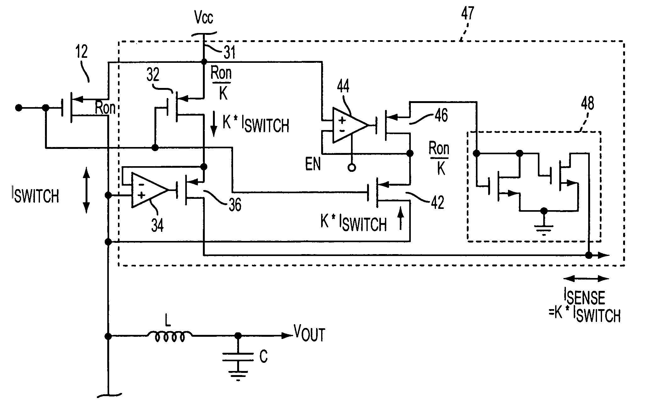
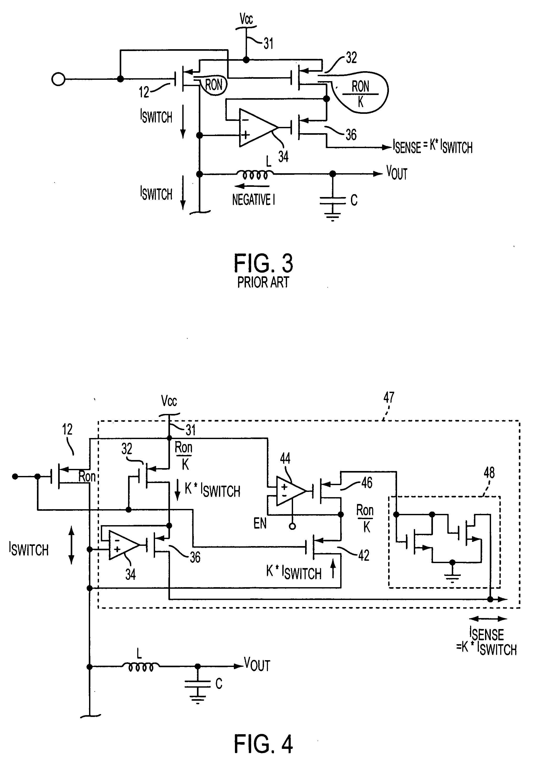
[0030] As noted above, the present invention provides for substantially loss-less sensing of the current flowing though the high-side switch in both a positive and negative direction. FIG. 4 illustrates an exemplary embodiment of the present invention. In comparison to the device illustrated in FIG. 3 and explained in further detail below, the present invention includes an additional replica device, which allows for sensing of the current flow in the neg...


PUM


Abstract

A current sensing circuit for use in a switching regulator having a high-side switch. The current sensing circuit includes a first sensing circuit coupled to the high-side switch for measuring current flowing in a positive direction through the high-side switch. The first sensing circuit includes a first replica device for generating a current which is a scaled version of the positive current flowing through the high-side switch. The current sensing circuit further includes a second sensing circuit coupled to the high-side switch for measuring current flowing in a negative direction through the high-side switch. The second sensing circuit includes a second replica device for generating a current which is a scaled version of the negative current flowing through the high-side switch.

Description

CLAIM OF PRIORITY [0001] This patent application, and any patent(s) issuing therefrom, claim priority to U.S. provisional patent application no. 60 / 604,014, filed on Aug. 25, 2004, which is incorporated herein by reference in its entirety.FIELD OF THE INVENTION [0002] The present invention relates to a method and apparatus for performing substantially lossless sensing of positive and negative peak inductor currents in a high-side switch, which may be utilized, for example, in a current mode switching regulator. BACKGROUND OF INVENTION [0003] The use of current mode switching regulators as a means of providing a predetermined and substantially constant output voltage to a variable load from a fluctuating voltage source is well known. FIG. 1 illustrates an example of the use of a high-side switch 12 in a trailing edge modulation current mode switching regulator. As shown in FIG. 1, the circuit I includes a controller 10 having a first output coupled to the high-side switch 12 and a se...

Claims


Application Information

Patent Timeline
Patent Type & Authority Applications(United States)
IPC IPC(8): H02M3/335
CPCG01R19/0092H02M2001/0009H02M3/156H02M1/0009
Inventor OSWALD, RICHARD K.YAMAMOTO, TAMOTSURYU, TAKASHI
Owner COLLABO INNOVATIONS INC
Why Eureka
Try Eureka